Is it common for the entire chassis to be 'chassis ground'?.
Yes.
It is why, amongst other reasons, the big transistors require insulators.
I can assure that the wiring is now correct after checking over and over again. The one mistake I did, in case you missed it in one of my postings, is out put wires, blue and black which I soldered reversed, blue to - and black to +. That could have made a big damage.
What could be "shorted input"
Thanks
What could be "shorted input"
Thanks
I'm assuming the output wires just go to the speaker sockets and that all the other circuitry is on the PCB (I've never actually built one or seen the boards for real) in which case reversing the leads would cause no operational issue at all, it would just invert the absolute phase to the speaker output.
I mentioned earlier that the bias pre-set should be able to swing the bias test point voltage considerably either way. If it does, then an audio signal should do the same and so if you have no sound at all then that implies that the audio input signal isn't getting as far as the C3/R10 junction.
If you touch the leads on C3 (the 10uF input cap) with a metallic screwdriver can you hear any click or noise ? Don't short the pins to anything, just touch one or the other.
What could be "shorted input"
Thanks
I was thinking of a short (whisker of wire etc) where you have soldered the input sockets.
Also you should be able to detect some kind of initial noise/thump from the speaker as the large coupling cap charges.
With no speaker connected and switching the amp ON (after it has been off a minute or so) should let you see an initial 'kick' of DC voltage across the speaker output terminals as the large cap charges.
As before, its all about gathering evidence.
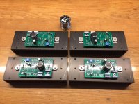
Amps are coming along, pretty much just have the wiring left to do.
newbie builder here.
My question here is how does one check or test for shorts etc? I can visually see that my solder connections look good (lol, I think so, all considering), but obviously that doesn’t tell the whole story. So what would be the procedure here. Yes I googled, etc. please advise and thanks in advance
Amps are coming along, pretty much just have the wiring left to do.
newbie builder here.
My question here is how does one check or test for shorts etc? I can visually see that my solder connections look good (lol, I think so, all considering), but obviously that doesn’t tell the whole story. So what would be the procedure here. Yes I googled, etc. please advise and thanks in advance
I would check if any soldered place has beep to ground, check the rca connectors not to beep between the signal and ground, make sure the v+ to power on does not touch the main ground wire, that you have ground to all elements grounded in pcb, that any of the mosfet legs have ground and i dont remember anything more atm....
I was thinking of a short (whisker of wire etc) where you have soldered the input sockets.
Also you should be able to detect some kind of initial noise/thump from the speaker as the large coupling cap charges.
With no speaker connected and switching the amp ON (after it has been off a minute or so) should let you see an initial 'kick' of DC voltage across the speaker output terminals as the large cap charges.
As before, its all about gathering evidence.
No such initial "kick" of DC voltage. It showed only .003v On the good board there was 2.+v initial kick.
On the good board, there is grunt or growl noise on the speaker upon power on and loud thump when powering off.
On the bad board silent, on power on and off.
Thanks for the responses. Since (lol, last September) I've been slowly putting together a pre amp, and the bells and whistles that I have added, and being a dad of a lil 2yo have slowed the pace of that project. The upside is I have been reading and learning so much during that time from all of you through these various threads on here. But at the end of the day I'm still the equivalent of the newbie 101 freshman year, while most of you are like Phd expert levels.... AKA there is so much I don't understand yet.
My dum dum questions:
1. I have extra washers and nuts (Please tell the there are extras in the kit)
2. "Beep" to Ground... Is there a thread that explains that to a neophyte such as myself. I googled "beep to ground"... I could figure out that I grab the DMM set it to the ohm position, and can place one lead on V+ for example and the other lead on say the heatsink??? for ground??? and I get O.L for infinite resistance and that happens (lol, doesn't mean I understand it). Am I in the right ballpark here? Granted anything combo yields O.L for me other than if place a lead on each side of a part like a resistor for example.
I'm a lil lost when it comes to this part, everything I have done so far looks exactly like the pictures, and I want the magic smoke to stay inside.
No such initial "kick" of DC voltage. It showed only .003v On the good board there was 2.+v initial kick.
On the good board, there is grunt or growl noise on the speaker upon power on and loud thump when powering off.
On the bad board silent, on power on and off.
First thing to do is to confirm the amp is still behaving itself and that it still has around +12 volts on the appropriate test point.
If it has, then the lack of noise at switch on and switch off has to be down to an open circuit connection or print. As before, measure voltages on the component leads themselves to be sure. The 12 volts bias voltage should be measurable on the positive end of C1 (the large speaker coupling cap). The negative end should see this 'kick' on power on/off and that point should carry through to the negative speaker terminal.
The positive terminal should have direct continuity to ground.
Something else to check... assuming the 12 volts is correct, does the faulty channels FET's heat up in the same way as the good channel. I'm sure they will but its one more easy check and it confirms that approximately the correct current is flowing. If by chance they were running cold then that would point to no or very low bias current and that would give similar symptoms of no switch on thump and no sound (at least for low level input voltages).
My dum dum questions:
1. I have extra washers and nuts (Please tell the there are extras in the kit)
I thought having a pile of bits left over was the sign of a true tech
")
My dum dum questions:
2. "Beep" to Ground... Is there a thread that explains that to a neophyte such as myself. I googled "beep to ground"... I could figure out that I grab the DMM set it to the ohm position, and can place one lead on V+ for example and the other lead on say the heatsink??? for ground??? and I get O.L for infinite resistance and that happens (lol, doesn't mean I understand it). Am I in the right ballpark here? Granted anything combo yields O.L for me other than if place a lead on each side of a part like a resistor for example.
All meters behave a little differently. Also it might be expected for a meter not to read OL (open circuit) when you think it should simply because of stray in circuit resistances.
Readings always need a bit of interpretation. If you read a dead short (say under 1 ohm) when checking whether a transistor is insulated from a heatsink for example then the chances are it isn't and the 1 ohm is real. If you read from a plus rail to the heatsink then you could get any combination of results, OL, beeping or a near short and the reason is because of the way other components are interacting are connected.
If the negative rail is grounded to chassis then any reservoir caps across the rail will interfere, any cap with residual voltage on it will also totally skew a reading.
So it all comes down to experience and knowing what to expect.
Really low value resistors (say under 1k) stand a good chance of being able to be checked in circuit, values under 10 ohm definitely so.
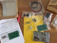
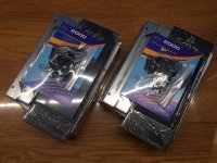
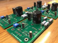
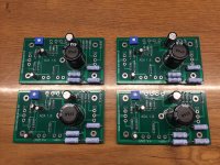
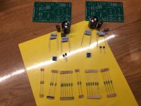
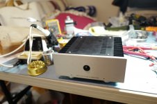
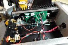
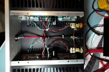
Started my build today! Two amps going to be used as mono’s. Am I doing something wrong by the looks of the attached pictures?
Next is wiring. I want to use N5 silver wires as in all my builds and interlink and speaker cables.
I also want to mount (after measuring and listening) a Capacitance Multiplier to get rid of a couple of mV of noise from the SMPS. Are there more DIY having good experiences with CM in the ACA? Or is it not wise?
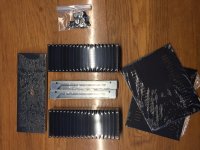
Last but not least the black panel of course with some laser engraving to see some UI signs as stated in my previous post some pages back.
Next is wiring. I want to use N5 silver wires as in all my builds and interlink and speaker cables.
I also want to mount (after measuring and listening) a Capacitance Multiplier to get rid of a couple of mV of noise from the SMPS. Are there more DIY having good experiences with CM in the ACA? Or is it not wise?
Last but not least the black panel of course with some laser engraving to see some UI signs as stated in my previous post some pages back.
Attachments
-
 6D04463C-4B13-4320-B66C-6F81CB4916C9.jpeg416.2 KB · Views: 345
 -
 D06B5D31-EC39-47FD-8D11-FE27DF23B4AA.jpeg334.2 KB · Views: 164
 -
 D6290AA1-0FAD-49BE-B00A-93E983BADDD7.jpeg457.3 KB · Views: 162
 -
 544E0F1C-1FF9-43E8-8C57-B702A6165153.jpeg478.5 KB · Views: 143
 -
 BF8600DC-6953-456B-AED7-1BEAED24509A.jpeg496.9 KB · Views: 309
 -
 F8A57167-EAD8-4031-B645-705FA4FE6BFA.jpeg428.9 KB · Views: 316
 -
 F94EB754-5C6D-4147-8544-42B6089267A5.jpeg603.6 KB · Views: 324
 -
 A8BE50C3-781C-4122-89E9-1932697A534D.jpeg427.3 KB · Views: 347
Last edited:
I'm assuming the output wires just go to the speaker sockets and that all the other circuitry is on the PCB (I've never actually built one or seen the boards for real) in which case reversing the leads would cause no operational issue at all, it would just invert the absolute phase to the speaker output.
I mentioned earlier that the bias pre-set should be able to swing the bias test point voltage considerably either way. If it does, then an audio signal should do the same and so if you have no sound at all then that implies that the audio input signal isn't getting as far as the C3/R10 junction.
If you touch the leads on C3 (the 10uF input cap) with a metallic screwdriver can you hear any click or noise ? Don't short the pins to anything, just touch one or the other.
No click or noise on C3. Voltages on Q1 & Q2 and resistors almost the same.
No click or noise on C3. Voltages on Q1 & Q2 and resistors almost the same.
On the non sounding board:
S 12.65v D 24.15v G 16.92v r1 12.25v-12.60v r2 12.23v-12.56v
r3 11.70v-12.19v r4 116.69v-12.19v
On the good board: all practically the same.
What has C2 got to do with the circuit?
Last edited:
I'm sorry for the very poor choice of words there.... 2. "Beep" to Ground... Is there a thread that explains that to a neophyte such as myself...
I meant checking for continuity between the MOSFETs and the Heatsinks. On most DMMs I know, there is a special mode of checking resistance which 'beeps' if current flows more or less 'freely' between to points. So yeah, putting one probe to the mosfet's central pin and the other to the heatsink (or ground) should not 'beep'.
Best,
Rafa.
Hi fellow DIYs,
I just completed the build and been listening to the V1.6 aca amp kit and I have to say WOW! My initial thought was to get this amp for my office PC audio setup. Building from it kit wouldn’t be a problem for me since my profession was an electro-mechanical engineer.
I like the enclosure design, simple and good looking. The PCB layout was well thought out. I like the idea of a separate power supply unit to eliminate the need to build a power supply.
Building the PCB assembly with through hole parts is so much easier than the SMT components I normally deal with. The chassis assembly was also pretty easy but replace the supplied M4 screws with socket head screws. I didn’t care for the screws supplied for the top and bottom covers so I ended up tapping those holes for M4 button head socket screws.
Initial power up:
It’s a good sign when you don’t see any sparks, smoke or a pop! After 5 minutes I biased the boards to 10V and after visiting the forum learning the 24V supply should be biased to 12V which I did.
Initial sound test:
As a sound source I used a Sony HiRes Walkman but it the not enough juice to drive the amp. I happen to have a Fii0 Mount Blanc headphone amp which did the job. For speakers I had a pair of 2 Pi speakers I used. I just placed these in my living room just and WOW! I was liking the sound.
After a day of listening I tried an old pair of Klipsch Hersey II speakers to the aca amp. Again WOW! The little aca amp had no problems driving the Hersey II very loud. Again, I was spending time into the late evening listening to my music library.
Connect to my main speakers:
After being impressed with this amp I decided to use the aca amp in my main system rather than my office PC audio system.
If you can afford and have the room, Klipsh La Scalla II speakers are my recommendation for this great sounding aca amp which are the speakers in my system. I since replaced the Fii0 Mount Blanc headphone amp with a Sony PHA-1A usb dac headphone amp and used to drive the aca amp.
The things I like:
- Dead quiet, no background noise even on the highly sensitive La Scalla II
- Engaging sound wants me to sit there and listen to the music
- Engaging sound, my toe keeps tapping to the music.
The thing I don’t like:
- Runs hot! I measured 125F on the fin side of the heatsink.
Thanks to Nelson Pass, DIYAudio for supplying a great value amp and 6L6 supplying build information!
Regards
Cat
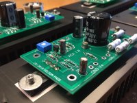
I added a few pics of my aca amp build.
I just completed the build and been listening to the V1.6 aca amp kit and I have to say WOW! My initial thought was to get this amp for my office PC audio setup. Building from it kit wouldn’t be a problem for me since my profession was an electro-mechanical engineer.
I like the enclosure design, simple and good looking. The PCB layout was well thought out. I like the idea of a separate power supply unit to eliminate the need to build a power supply.
Building the PCB assembly with through hole parts is so much easier than the SMT components I normally deal with. The chassis assembly was also pretty easy but replace the supplied M4 screws with socket head screws. I didn’t care for the screws supplied for the top and bottom covers so I ended up tapping those holes for M4 button head socket screws.
Initial power up:
It’s a good sign when you don’t see any sparks, smoke or a pop! After 5 minutes I biased the boards to 10V and after visiting the forum learning the 24V supply should be biased to 12V which I did.
Initial sound test:
As a sound source I used a Sony HiRes Walkman but it the not enough juice to drive the amp. I happen to have a Fii0 Mount Blanc headphone amp which did the job. For speakers I had a pair of 2 Pi speakers I used. I just placed these in my living room just and WOW! I was liking the sound.
After a day of listening I tried an old pair of Klipsch Hersey II speakers to the aca amp. Again WOW! The little aca amp had no problems driving the Hersey II very loud. Again, I was spending time into the late evening listening to my music library.
Connect to my main speakers:
After being impressed with this amp I decided to use the aca amp in my main system rather than my office PC audio system.
If you can afford and have the room, Klipsh La Scalla II speakers are my recommendation for this great sounding aca amp which are the speakers in my system. I since replaced the Fii0 Mount Blanc headphone amp with a Sony PHA-1A usb dac headphone amp and used to drive the aca amp.
The things I like:
- Dead quiet, no background noise even on the highly sensitive La Scalla II
- Engaging sound wants me to sit there and listen to the music
- Engaging sound, my toe keeps tapping to the music.
The thing I don’t like:
- Runs hot! I measured 125F on the fin side of the heatsink.
Thanks to Nelson Pass, DIYAudio for supplying a great value amp and 6L6 supplying build information!
Regards
Cat
I added a few pics of my aca amp build.
Attachments
Started my build today! Two amps going to be used as mono’s. Am I doing something wrong by the looks of the attached pictures?
Next is wiring. I want to use N5 silver wires as in all my builds and interlink and speaker cables.
I also want to mount (after measuring and listening) a Capacitance Multiplier to get rid of a couple of mV of noise from the SMPS. Are there more DIY having good experiences with CM in the ACA? Or is it not wise?
Last but not least the black panel of course with some laser engraving to see some UI signs as stated in my previous post some pages back.
The SPMS has a very good, broad spectrum/frequency capacitor decoupling combination at its output. I would expect that such rail decoupling would not need any further attention... By the way, its negative DC output is connected to the mains IEC ground pin.
With silver (which I use extensively as well), just a word of caution - silver will emphasize high-frequency spectrum, unless you use a lot of parallel runs for each conductor (3 runs for each conductor would be ok). You could try a parallel run of silver and copper, for each conductor... or, silver, copper, and gold-plated-copper.
Silver ribbons are fantastic - they will give an open, very fast sound with a lot of high-frequency extension.
Copper - perfect for mids
Gold plated copper - good for bass frequencies.
Having in mind that a 2 gain pure class A amplifier is fast & revealing by definition, you would definitely want to include some copper there, or gold-plated copper.
Just my 2 cents.
Hi guys. Just a quick question. I’ve got nylon standoff’s to connect the pcb to the heat sink. I’m I in trouble? Does the stand-off need to be brass for earth connection?
I am pretty sure that the chassis will be floating, with a nylon standoff...
To elaborate a bit: the SMPS has a direct DC connection between the mains earth pin, and the DC supply negative conductor (I confirmed it). The PCB has two large eyelets that allow DC negative connection to the heatsink; one of which is the large middle eyelet. So, if you use a nylon standoff, there will be no connection between mains earth pin (DC negative wire), and chassis.
Last edited:
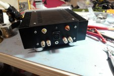
OK... what is the secret to soldering the center pins / half scoop looking pin that are on either the RCA inputs or on the power connector?
You need enough heat. If the object (half scoop pin) doesn't reach the same temperature as the solder, the solder won't stick to the pin.
With low wattage soldering irons, say 20Watt and lower, it can be a problem to get enough heat across. 40W irons shouldn't have a problem, but be careful not to damage the plastic rings on the RCA sockets.
.
- Home
- Amplifiers
- Pass Labs
- Amp Camp Amp - ACA