I got my kit a little while ago, and still haven't warmed up the iron to dig in to the project. I didn't buy the chassis, because I'm going to mount the amps to a bulkhead in a sailboat I'm refitting. I found some big flat heatsinks I'm hoping will work; I guess I'll find out soon enough. If not, I'll find bigger ones. ") There's a reference somewhere to "the new 2U UMS 8 hole pattern." Does anyone have specs for, specifically, the 3 holes for the transistors and board? I couldn't find that anywhere. Sure, I could measure it, but I thought I'd ask.
There's a reference somewhere to "the new 2U UMS 8 hole pattern." Does anyone have specs for, specifically, the 3 holes for the transistors and board? I couldn't find that anywhere. Sure, I could measure it, but I thought I'd ask.
I plan to power the amps from the 12v 1000Ah battery bank. I have a step-up converter on my B1 that just works like magic. I'm hoping a pair of those step-up converters on the ACA's will work as nicely. Would I be able to control the power consumption by dialing the voltage down to, say, 16v? Most of the power is from solar, and there's just only so much of it.
I'll post cool photos, and ask more silly questions as I go.
Thanks!
There's a reference somewhere to "the new 2U UMS 8 hole pattern." Does anyone have specs for, specifically, the 3 holes for the transistors and board? I couldn't find that anywhere. Sure, I could measure it, but I thought I'd ask.I plan to power the amps from the 12v 1000Ah battery bank. I have a step-up converter on my B1 that just works like magic. I'm hoping a pair of those step-up converters on the ACA's will work as nicely. Would I be able to control the power consumption by dialing the voltage down to, say, 16v? Most of the power is from solar, and there's just only so much of it.
I'll post cool photos, and ask more silly questions as I go.
Thanks!
I checked everything:
- that there is no shorts anywhere
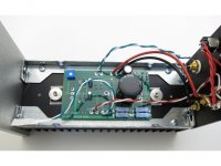
- that MOSFETs are not shorted against the heatsink (middle leg should not beep continuity with the heatsink)
- I actually measured every expected value on their 'next' points... so I measured a resistor one 'hole' ahead and one hole before to make sure everything was properly soldered and with their correct values (which I did measure beforehand as well)
- make a final visual inspection that every cap and transistor is oriented correctly (I had one soldered the other way around)
Be sure to first power up the amp without any input source or speakers! Once you start it up, I tried to quickly assess that the bias current is not beyond the 12V mark. And then, just work slowly.
That's about it!
Thank you again for your kind reply.
So o checked and rechecked and all seems correct.
I cant find any shorts, the mosfets dont beep against chassis, any leg from them, all seems correctly oriented and i am still afraid to power it up lol...
As i dont have alligator connectors with me i am going to buy them and then i'll make the 1st power on.
Just to make sure i have this right, on the back on the speakers connectors, the red ones are the out+ from pcb right? So what is ground from the back pannel wires is the speaker + on the back? That is correct?
This is also chassis ground.
In terms of my security,
What is the size / dimensions of the heatsink in the current kits with 24v power supply .. in the kit description it's given to be 40mm thick/long fins .. what are the other dimensions of it ?
200mm length x 80mm height x 40mm 'fins' depth.
See here Mini Dissipante 2U – diyAudio Store
Just to make sure i have this right, on the back on the speakers connectors, the red ones are the out+ from pcb right? So what is ground from the back panel wires is the speaker + on the back? That is correct? This is also chassis ground.
Yes. And yes it is confusing. The 'Red' output terminals are connected to the Ground wires.
Make sure it is like Step 35 of the build guide.
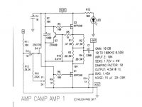
It conforms to the circuit diagram Step 1 that is '+ OUT' connected to 'ground'.
Alan
Attachments
Last edited:
Yes. And yes it is confusing. The 'Red' output terminals are connected to the Ground wires.
Make sure it is like Step 35 of the build guide.
It conforms to the circuit diagram Step 1 that is '+ OUT' connected to 'ground'.
Alan
Thank you for your reply.
So i really think i have all correct.
So next step is to power it on, quickly measure both channel bias and if is under 12v each, let it warm up for like 20 minutes and the dial in the bias.
Is this correct?
Let me just report to you the S now measures about 12.+ v so are resistors 1 2 3 & 4 all ends. Resistors 3 & 4 are a little lower at 11.6 v. on the other ends.
However, there is no sound coming when connected to a speaker.
The other board also measures similarly and there is sound coming out.
The DC conditions appear to be correct now which is 95% of the way there really. If the bias pre-set works correctly and is able to swing the voltage on those four resistors by a good amount (say down to 7v volts and up to 18v then your problem has to be either no continuity of the audio signal to the input coupling cap C3, or no speaker continuity from the output coupling cap to the speaker sockets. Or something like a short at the input or speaker sockets.
fred0 yes. This is from post #5165
Maybe there needs to be step 42a. Something like - ''now have a drink of your choice, inspect the wiring and boards again and once you are happy plug in and switch on (no need for input or speakers at this stage)''.
You should measure the bias voltage when you first switch it on, as much to make sure all is well as anything else. Then set it roughly to half the supply voltage 10 /12 volts (10 volts for 19 volt supply and 12 volts for the 24 volt supply) and let it all warm up.
Check again after 5 or 10 minutes and adjust it closer to the 10 or 12 volt setting.
Note the bias will change with temperature, so you have to wait for the heatsinks to reach their stable temperature (not getting any hotter so 30 minutes or so) before making the final adjustment.
Now is the time to try it with speakers and music and enjoy.
Alan
Ok, so the amp powers on and nothing exploded, melted, burned or killed me
I notice that on power on the voltage starts about 10-11v and goes up to about 12,4v then starts to drop, same thing in both channels. As i dont have crocodile tips i will have to wait until monday to get them and bias accordingly.
Anyway, even if more spoon fed i could not be, i am HAPPY \o/
Thanks to all that took the time to respond to my noob questions!
You all rock!
Now Luxembourg has a class A addict noob diyselfer!!!!
I did what you recommended and all related measurements were now at what mooly told me to be so if I understand him correctly.
However there is no sound coming out on this channel. The other one has.
It looks like another problem.
Thanks for your help.
Check/compare input and output wiring between the working and the non-working side. Could be something as simple as a shorted input, or something more complicated. Post some pictures.
Hi guys. Just a quick question. I’ve got nylon standoff’s to connect the pcb to the heat sink. I’m I in trouble? Does the stand-off need to be brass for earth connection?
My kit had the nylon standoffs too. They worked fine going into the heatsink, but be careful not to overtighten the screw that holds down the PCB. You can strip it out quite easily.
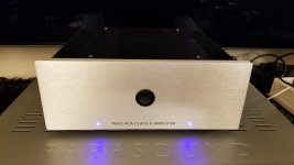
Congrats Motospark! Looks great! And I agree that matching leds of the preferred color it the way to go.It is alive with Blue LEDs now. Thanks for all your help with the purchasing of the correct LEDs.
Best regards,
Rafa.
Friends, I have a quick question, specially reading this note from fred0
When I was building mine, the Source leg of Q2 beeped against the heatsink. I panicked, but upon reading the skematic, that is connected to ground. So I started checking, and due to the nature of my case, the Heatsinks are actually ground. The standoffs from the PCBs are also ground. And, while the anodized surfaces are NOT conductive, the sides which don't have the anodizing layer ARE also ground.
Is this is a problem and something to be avoided in the future? Is it common for the entire chassis to be 'chassis ground'?
Thanks in advanced,
Rafa.
...the mosfets dont beep against chassis, any leg from them...
When I was building mine, the Source leg of Q2 beeped against the heatsink. I panicked, but upon reading the skematic, that is connected to ground. So I started checking, and due to the nature of my case, the Heatsinks are actually ground. The standoffs from the PCBs are also ground. And, while the anodized surfaces are NOT conductive, the sides which don't have the anodizing layer ARE also ground.
Is this is a problem and something to be avoided in the future? Is it common for the entire chassis to be 'chassis ground'?
Thanks in advanced,
Rafa.
Thanks
Hi Rafa, thanks, I ended up purchasing a Blue LED kit from PartsExpress, it was only couple of dollars and came with 10 LEDs and pull down resistors, 100 and 470, I used them as is. They are a little bright but I like them like that.
Congrats on your Custom build, It looks beautiful.
Mark
Congrats Motospark! Looks great! And I agree that matching leds of the preferred color it the way to go.
Best regards,
Rafa.
Hi Rafa, thanks, I ended up purchasing a Blue LED kit from PartsExpress, it was only couple of dollars and came with 10 LEDs and pull down resistors, 100 and 470, I used them as is. They are a little bright but I like them like that.
Congrats on your Custom build, It looks beautiful.
Mark
- Home
- Amplifiers
- Pass Labs
- Amp Camp Amp - ACA