No, just with the wall warts provided in the kit. Will it make a difference?
5v extra in a small amp is a big increase = 26%.
See what Rudi wrote here in another thread
Gentlemen, when I have listened to the sound of the ACA#1 for the 1st time, I have been disappointed a little (a lot).
Well, I thought, this is how "ClassA" sounds - no "joie de vivre", the internal rhythm has been missing.
I has not been until I have been told to operate the ACA#1 from a 24VDC(!) PSU that I have changed my mind (my ears) to listen to the ACA#1 more closely, and: this advice has been perfect!
Best regards - Rudi_Ratlos
Last edited:
Thanks for the reply. What will this achieve? I am hesitant to modify Nelson's design which sounds great with my chr70s and Monacors. And also because the amps are cased up!
try no feedback , or 150k instead of 68,1k
Thanks, this will be easy to try out (i have 1 already) but I'm not sure it will address what appears to be a shortcoming (or characteristic) of the little Fe108es.
So any suggestion for implementing a correction network? Series or parralel (as with current source)? Inductor with resistor? Only resistor?

So any suggestion for implementing a correction network? Series or parralel (as with current source)? Inductor with resistor? Only resistor?
5v extra in a small amp is a big increase = 26%.
See what Rudi wrote here in another thread
Thanks for the reply. What will this achieve? I am hesitant to modify Nelson's design which sounds great with my chr70s and Monacors. And also because the amps are cased up!
increase the nearest output impedance F2
")
You'd be better off building the BAF hockey puck amp which is based on the same type of topology. At this point in time you wouldn't call it a beginners amp though so if you want a proven design to drive difficult loads, BA2, or BA3 with about 6 pairs of mosfets on the output will certainly drive 2 Ohms with relative ease.Will the ACA handle a 2 ohm load?
Thanks for the advice.
I upgraded the power supply into my ACAs to 24V. Would I need to adjust the drain voltage to match the power supply? I'm guessing not since I haven't seen that mentioned elsewhere.
You will want to adjust P1 so that instead of having 10V, you have slightly higher than half your supply voltage so that you will clip more evenly. Adjust it to about 12.5 V with a 24 V supply.
If lower distortion is the goal, the quality of C2 is probably more important than the value. Simulation might not reveal this.
The extra Gate capacitance of the IRFP150 will cause an increase in distortion at high frequencies. Have you tried adjusting R4, R5 and R9?
R1-4 have a major effect on the 2nd order distortion and overall linearity. I have experimented with these and plotted results in this thread. See posts 274 and 284.
Thanks Loudthud,
I wouldn't say lower distortion is THE goal, but of course it's preferable to higher distortion. The goal is just to have a working amp that sounds good... whether that can be achieved with the IRFP150s I don't know. I guess I'm the guinea pig. I chose the 150s just for a little more oomph, and to try something different as I've already built stock ACAs.
I'm probably the wrong person to be trying this mod since my knowledge of electronics is pretty thin (my forte is in the fabrication). However, as I said before, this is low cost/low risk experimentation, and I can alway swap in the standard components if it doesn't work. If nothing else I'll learn a thing or two, maybe.
I'll try tweaking the R values you've suggested and see what the simulation produces. (BTW, did you mean R6 and not R4?). Of course I realize that it's only a simulation and is of limited value, especially since I'm not really sure of how the graphs relate to real-world performance.
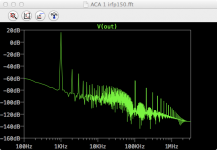
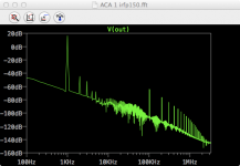
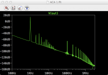
Just for kicks, I've attached some FFT graphs. The first is the IRFP150 mod with C2 = 1000uF. Second is C2 = 100uF. Third is the original ACA as designed by NP.
I wouldn't say lower distortion is THE goal, but of course it's preferable to higher distortion. The goal is just to have a working amp that sounds good... whether that can be achieved with the IRFP150s I don't know. I guess I'm the guinea pig. I chose the 150s just for a little more oomph, and to try something different as I've already built stock ACAs.
I'm probably the wrong person to be trying this mod since my knowledge of electronics is pretty thin (my forte is in the fabrication). However, as I said before, this is low cost/low risk experimentation, and I can alway swap in the standard components if it doesn't work. If nothing else I'll learn a thing or two, maybe.
I'll try tweaking the R values you've suggested and see what the simulation produces. (BTW, did you mean R6 and not R4?). Of course I realize that it's only a simulation and is of limited value, especially since I'm not really sure of how the graphs relate to real-world performance.
Just for kicks, I've attached some FFT graphs. The first is the IRFP150 mod with C2 = 1000uF. Second is C2 = 100uF. Third is the original ACA as designed by NP.
Attachments
Hi Guys, just starting to build another ACA (my third now). I just have the pcb's completed with the 6w resistor mod and have always gone with the laptop power supplies previously but wanted to build a linear power supply for this one partly as a learning process. So am looking at suitable transformers with around 18v dual outputs which should give me a little flexibility on the final dc output to try running at higher biases such as the 24vdc mentioned recently (or getting close) but what sort of current requirement would I need the transformer to have for a good safety margin for this?
Cheers
Jamie
Cheers
Jamie
I have too much on the back burner at the moment but if it was me looking for a small incremental project I would try the zen variations part 4:
https://www.passdiy.com/project/amplifiers/zen-variations-4
with a 48v@3A wall wart such as:
AC 100 240V to DC 48V 3A 120W Power Adapter Port 5 5mm x 2 5mm for Poe Switch | eBay
It is similar to the amp camp in topology, but has only 0.08% distortion at 1W verses the amp camp with %0.7. I wonder if it is the Pass Labs Aleph modulated current source or the higher rails that provides 9 fold lower distortion? And just like the ACA it was designed by the legendary Nelson Pass so it must sound good.
Last edited:
Linear Power Supply Issues
Hi,
I've constructed the ACA amp with a linear power supply consisting of a:
-15VAC transformer
-Rectifier
-PI Filter CRC
The amp works and plays, but the issue is frequency response dips several db from about 1kHz to 6kHz. It has more gain from 100Hz to 900Hz, and lots of gain at 20kHz to 200khz.
I've tried different rectifiers (fast and slow) with similar results
I've changed the CRC PI filter from 8800uF to 66000uF with slightly better results.
I've also tried and LT3080 and LT3083 regulator with similar results
My Kepco bench power supply also has similar results
The amp is not starved of current. I'm always measuring about 0.9A using different multimeters. Voltage is about 18VDC. Bias is 10VDC I'm just not getting an even frequency response.
Can anybody explain why? Does this design really want a switching power supply?
Thanks.
Leo
Last edited:
- Home
- Amplifiers
- Pass Labs
- Amp Camp Amp - ACA