I've been working on a Mini Aleph build over the last month or so and wanted to share my progress here to get feedback and also to hopefully provide some helpful information for future builders. And to be fair I should mention that the "last month or so" actually refers to the following build schedule:
2007 - Bought a LM3886 kit from Chipamp.com and on a whim added some Aleph boards to the order.
2008? - Placed an order with ApexJr for some other parts and remembered the Aleph boards so I added some transformers to the order.
2009? - I was moving and didn't want to move my 12" sonosub so I traded it to another DiyAudio member for some capacitors and heat sinks for the Alephs. In a major coincidence Variac was going by that person's house and offered to drop off the sub for me and pick up the parts. We then both forgot about them for a year or two and they sat collecting dust at his house.
2011 - At Burning Amp Variac and I talked and remembered the Aleph parts, but weren't sure where they were hiding. I had written them off as donated to another project, but a few months later they appeared at my office. Variac kindly included some large aluminum C-channel for the amp enclosures.
February 2012 - Over four years after I bought the Aleph boards I purchased the rest of the parts and started the build.
At some point I'll try to get around to doing a full writeup, but for now here is an overview of the build and some photos.
- The Aleph boards and the two power supply boards are from Chipamp.com. Using separate power supplies for a 10-15w amp is probably overkill, but since the transformers were $8 and I had the capacitors I figured why not.
- Matched Transistors (Q1/Q2) were purchased from tech-diy.com.
- Transformers are Signal BL1752 from ApexJr. Primary 230V -> Secondary 48VCT 7A & 28VCT 3A. Primary 115V -> Secondary 24VCT & 14VCT. I'll be running these at 115V and using the 24VCT secondaries which should hopefully give me 14-16v rails. For now I am not using the resistors in the CRC on the power supply boards, I may add those later after measuring the ripple.
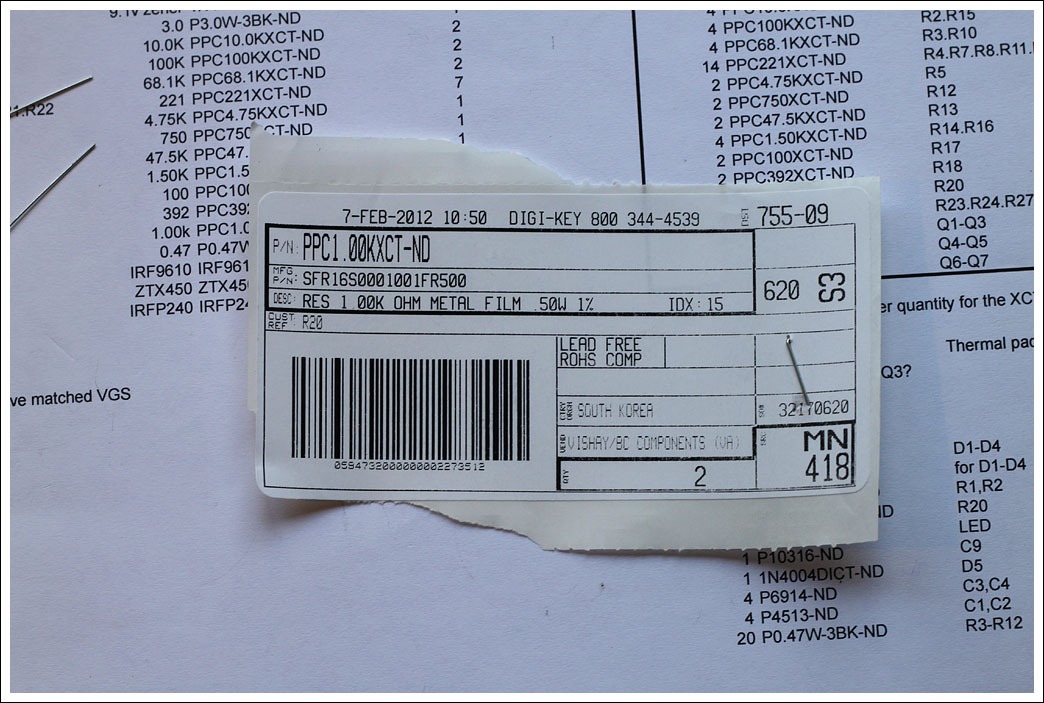
- The rest of the components were purchased at Digikey or ApexJr. One great thing about Digikey is that you can add customer notes to your BOM which are printed on the labels, this makes things really easy when you are doing the build since you don't have to lookup which part is which.
- The most difficult part of this project has been figuring out how to get power from the power supply unit to the amp. I needed a 7 pin plug, but I didn't want to spend a ton of money. The plan is to use a 7 pin aircraft connector ($8 on ebay), though I have concerns that the pins will be too small for the 14g wire I'm using, we'll find out.
- I'm targeting a bias current of 1.2-1.4A since I will be using this amp to drive 4 ohm speakers, and because I have the heatsink capacity. For now the amps are built using fixed value resistors, but I have some precision trim pots I can substitute for R13 to adjust the bias.
That's all of the pertinent information I can think of at the moment. Please feel free to post questions, comments, suggestions, etc. I'm really looking forward to firing these up to see how they sound.
2007 - Bought a LM3886 kit from Chipamp.com and on a whim added some Aleph boards to the order.
2008? - Placed an order with ApexJr for some other parts and remembered the Aleph boards so I added some transformers to the order.
2009? - I was moving and didn't want to move my 12" sonosub so I traded it to another DiyAudio member for some capacitors and heat sinks for the Alephs. In a major coincidence Variac was going by that person's house and offered to drop off the sub for me and pick up the parts. We then both forgot about them for a year or two and they sat collecting dust at his house.
2011 - At Burning Amp Variac and I talked and remembered the Aleph parts, but weren't sure where they were hiding. I had written them off as donated to another project, but a few months later they appeared at my office. Variac kindly included some large aluminum C-channel for the amp enclosures.
February 2012 - Over four years after I bought the Aleph boards I purchased the rest of the parts and started the build.
At some point I'll try to get around to doing a full writeup, but for now here is an overview of the build and some photos.
- The Aleph boards and the two power supply boards are from Chipamp.com. Using separate power supplies for a 10-15w amp is probably overkill, but since the transformers were $8 and I had the capacitors I figured why not.
- Matched Transistors (Q1/Q2) were purchased from tech-diy.com.
- Transformers are Signal BL1752 from ApexJr. Primary 230V -> Secondary 48VCT 7A & 28VCT 3A. Primary 115V -> Secondary 24VCT & 14VCT. I'll be running these at 115V and using the 24VCT secondaries which should hopefully give me 14-16v rails. For now I am not using the resistors in the CRC on the power supply boards, I may add those later after measuring the ripple.
- The rest of the components were purchased at Digikey or ApexJr. One great thing about Digikey is that you can add customer notes to your BOM which are printed on the labels, this makes things really easy when you are doing the build since you don't have to lookup which part is which.
- The most difficult part of this project has been figuring out how to get power from the power supply unit to the amp. I needed a 7 pin plug, but I didn't want to spend a ton of money. The plan is to use a 7 pin aircraft connector ($8 on ebay), though I have concerns that the pins will be too small for the 14g wire I'm using, we'll find out.
- I'm targeting a bias current of 1.2-1.4A since I will be using this amp to drive 4 ohm speakers, and because I have the heatsink capacity. For now the amps are built using fixed value resistors, but I have some precision trim pots I can substitute for R13 to adjust the bias.
That's all of the pertinent information I can think of at the moment. Please feel free to post questions, comments, suggestions, etc. I'm really looking forward to firing these up to see how they sound.
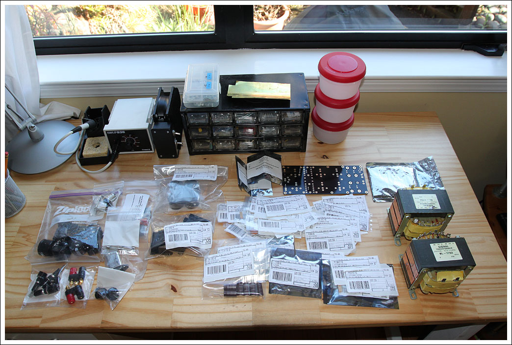
The stack of parts ready to go.
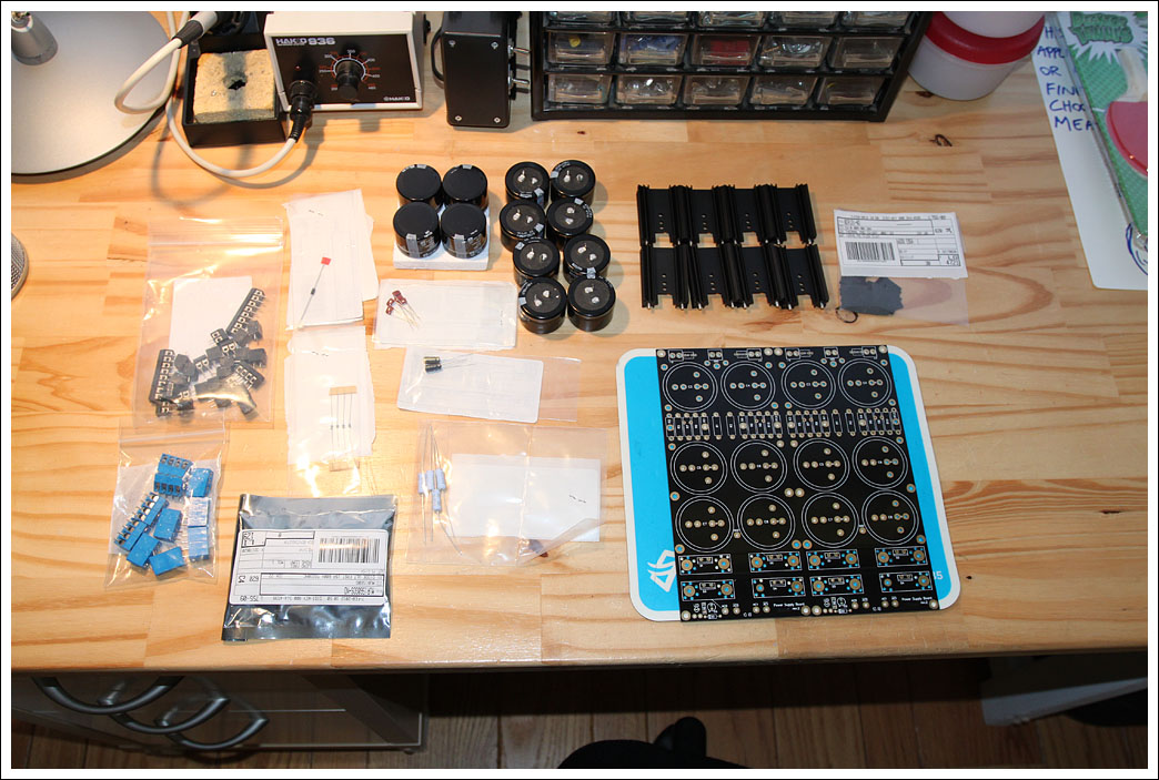
Here are the parts for the power supply boards. As part of the subwoofer trade I received 8 4700uF caps, I purchased 4 10000uF caps to use as the last set in the CRC filter. These are 10000uF instead of 4700uF so if/when I add the CRC resistors their value will not have to be too large to create an appropriate low-pass filter. The heatsinks for the rectifier diodes are 2" tall.
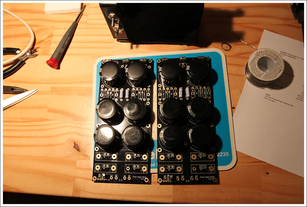
Capacitors and resistors installed. CRC resistors are jumpers for now.
The diodes are mounted to the heat sinks using Bergquist pads. Unfortunately I accidentally purchased non-insulating pads, which are fine in this usage since the heatsinks are electrically isolated, but is a problem for the MOSFETS in the amps. Doh. The screws were torqued as recommended by Bergquist using a small torque driver.
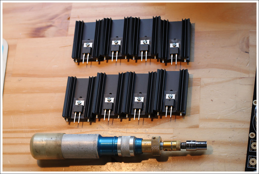
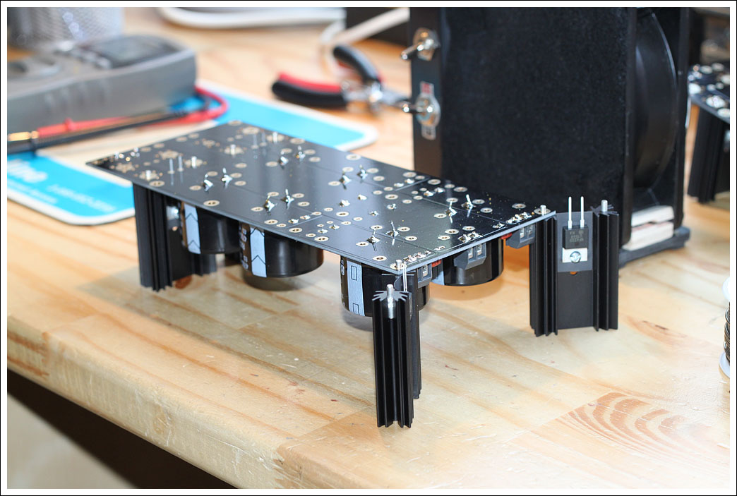
When installing the heatsinks the board is a bit unweildy, using the other heatsinks as temporary stands make things a lot easier.
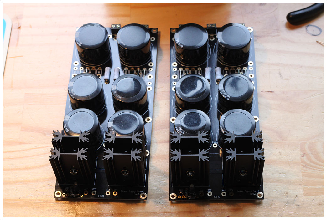
Power supply boards populated and ready to go.
Moving on to the amp boards. Digikey does not have the best prices on small lots of components, but it is very easy to get what you need there.
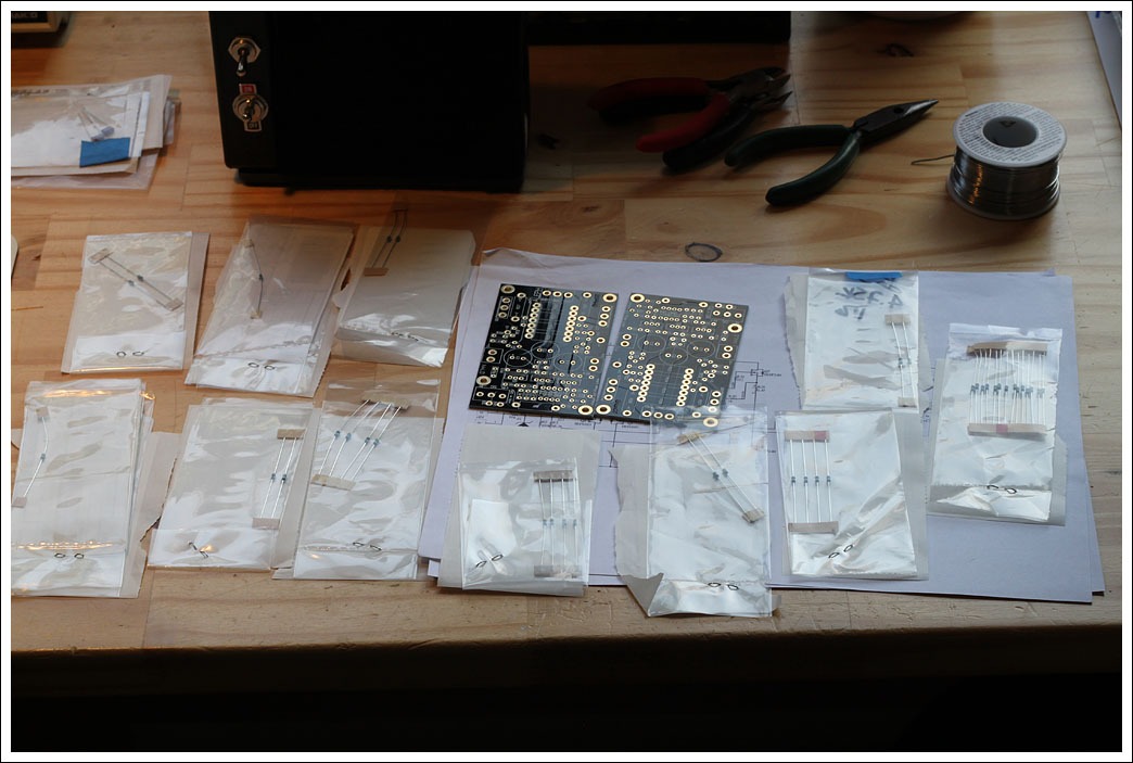
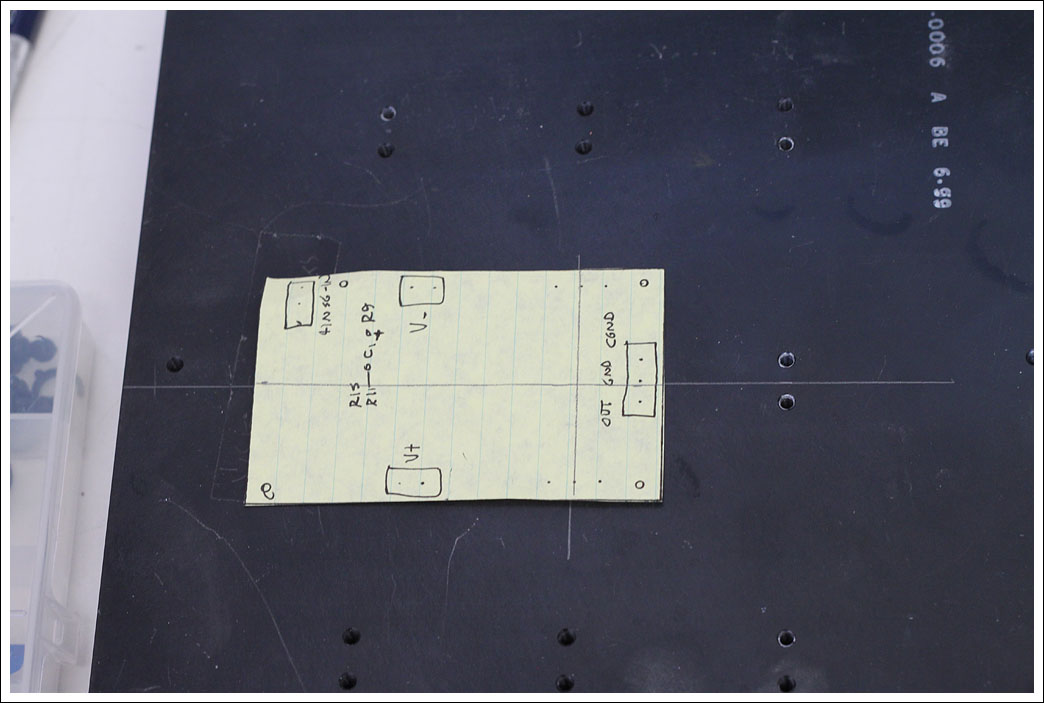
After placing the first few resistors I realized that all the labels were getting covered up so I took this picture so that I can locate parts later on. Also, it is a very good idea to do a tracing/photocopy of the boards before you populate them so you can use that tracing to lay out mounting points on your enclosure.
I included the parts numbers in the "cust ref" field in my BOM at digikey.com. This is printed on the labels and makes installation really easy, no hunting for parts by value.
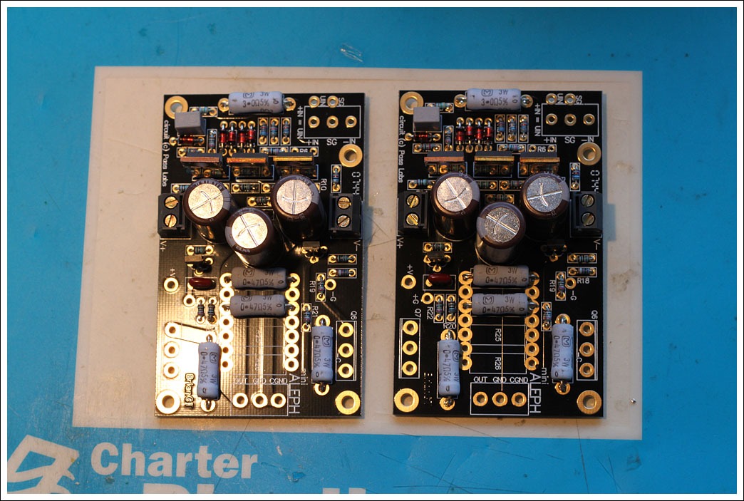
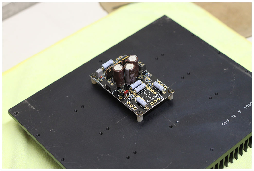
Both amp boards populated and ready to go. I upgraded the caps to Elna Simlic's when buying parts. I'm using screw terminals for the +/-V, but the audio connections will be soldered to make sure they are a solid connection.
More pictures are on the way... here's a preview of a key component of my enclosures.
- Matt
Here are the parts for the power supply boards. As part of the subwoofer trade I received 8 4700uF caps, I purchased 4 10000uF caps to use as the last set in the CRC filter. These are 10000uF instead of 4700uF so if/when I add the CRC resistors their value will not have to be too large to create an appropriate low-pass filter. The heatsinks for the rectifier diodes are 2" tall.
Capacitors and resistors installed. CRC resistors are jumpers for now.
The diodes are mounted to the heat sinks using Bergquist pads. Unfortunately I accidentally purchased non-insulating pads, which are fine in this usage since the heatsinks are electrically isolated, but is a problem for the MOSFETS in the amps. Doh. The screws were torqued as recommended by Bergquist using a small torque driver.
When installing the heatsinks the board is a bit unweildy, using the other heatsinks as temporary stands make things a lot easier.
Power supply boards populated and ready to go.
Moving on to the amp boards. Digikey does not have the best prices on small lots of components, but it is very easy to get what you need there.
After placing the first few resistors I realized that all the labels were getting covered up so I took this picture so that I can locate parts later on. Also, it is a very good idea to do a tracing/photocopy of the boards before you populate them so you can use that tracing to lay out mounting points on your enclosure.
I included the parts numbers in the "cust ref" field in my BOM at digikey.com. This is printed on the labels and makes installation really easy, no hunting for parts by value.
Both amp boards populated and ready to go. I upgraded the caps to Elna Simlic's when buying parts. I'm using screw terminals for the +/-V, but the audio connections will be soldered to make sure they are a solid connection.
More pictures are on the way... here's a preview of a key component of my enclosures.
- Matt
Last edited:
I'll be running these at 115V and using the 24VCT secondaries which should hopefully give me 14-16v rails. For now I am not using the resistors in the CRC on the power supply boards, I may add those later after measuring the ripple.
Matt: The transformer secondary (even wired at 115V) seems quite high. 24V x 1.41=33V. Getting down to 14-16V will take some large R's and burn some heat....
I'm pretty much exactly where you are in my build as well. I got few BrainGT boards from another member in a package deal with a few other things and I've decided to build the mini-A before building an F4.
Slomatt and Boywonder,
I remember an issue with the board marking for either C1 or C3. It seems as if one of them had the + next to the wrong pin. Before you connect the board for the first time I suggest you search the forum to see if your board has that mistake.
I remember an issue with the board marking for either C1 or C3. It seems as if one of them had the + next to the wrong pin. Before you connect the board for the first time I suggest you search the forum to see if your board has that mistake.

Audiosan: Good point!...sorry about that...It was early, before coffee!
Grimberg: I read that thread, and I recall someone mentioning that the silkscreen had a problem on the early blue boards, and was corrected on the black/gold boards.
Grimberg: I read that thread, and I recall someone mentioning that the silkscreen had a problem on the early blue boards, and was corrected on the black/gold boards.
Last edited:
I found the post. Maybe it refers to a different batch of the boards.
http://www.diyaudio.com/forums/pass-labs/52188-new-aleph-mini-pcb-gb-23.html#post630253
http://www.diyaudio.com/forums/pass-labs/52188-new-aleph-mini-pcb-gb-23.html#post630253
Audiosan: Good point!...It was early, before coffee!
Grimberg: I read that thread, and I recall someone mentioning that the silkscreen had a problem on the early blue boards, and was corrected on the black/gold boards.
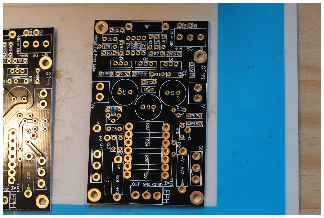
The BrianGT schematic shows the negative side of C1 being connected to R9 and R10, and the positive side to C4, R15, and R11.
On my boards (revision 0744, see photo above) the positive terminal of C1 connects to R9, which is the opposite of the schematic. I assumed the schematic was correct and the boards were wrong, but based on Brians's post you linked to it appears that the schematic is in fact incorrect and the boards are right.
The official Pass ALEPH30 schematic shows that C1 (marked as C11) as having it's positive lead towards the -IN, which matches the boards. Based on that it appears that I should de-solder and flip my capacitors.
- Matt
Bought my boards a couple of months ago:
An externally hosted image should be here but it was not working when we last tested it.
Pass DIY Addict
Joined 2000
Paid Member
Ha - that's a pretty funny story! Your speed of building an amp seems to match my own - seems that all of my projects span multiple years.
Congrats for finding the time (and parts from all those years ago) to get you build under way!
Congrats for finding the time (and parts from all those years ago) to get you build under way!
Everybody has seen populated Aleph boards before, time to move onto the fun part of the project. 🙂
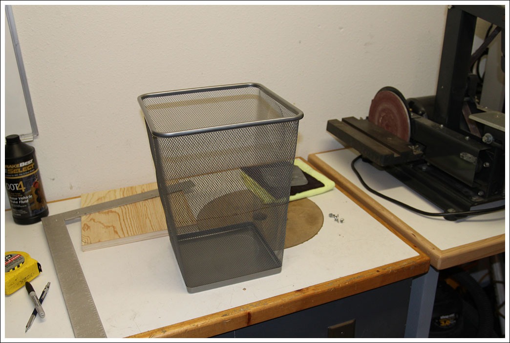
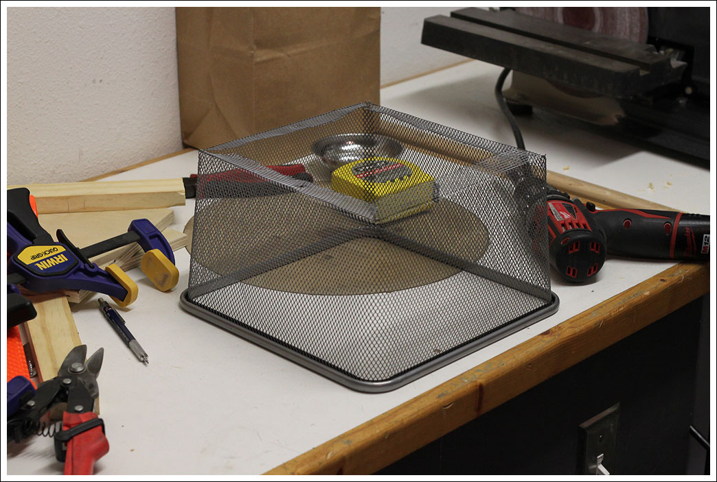
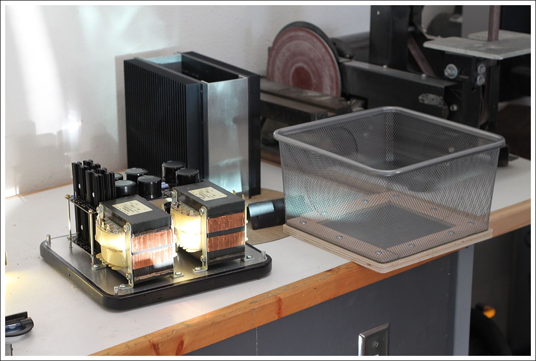
As with my Chipamps one of main components is an IKEA product, in this case a $5 garbage can. I needed a way to keep fingers out of the power supply, while still allowing for ventilation.
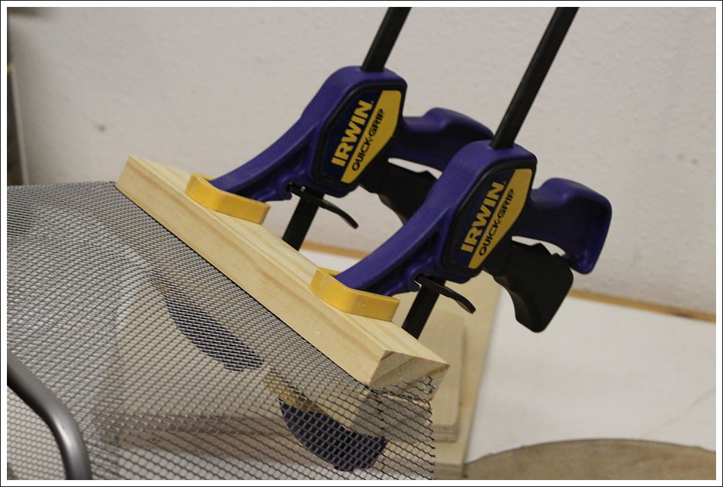
Abbreviated to to exactly proper height, give or take an inch or so.

Bending the edges, those are sharp and leave very nice cuts, and they are good for putting scrapes in your freshly painted parts.
The cage is about 6" tall.
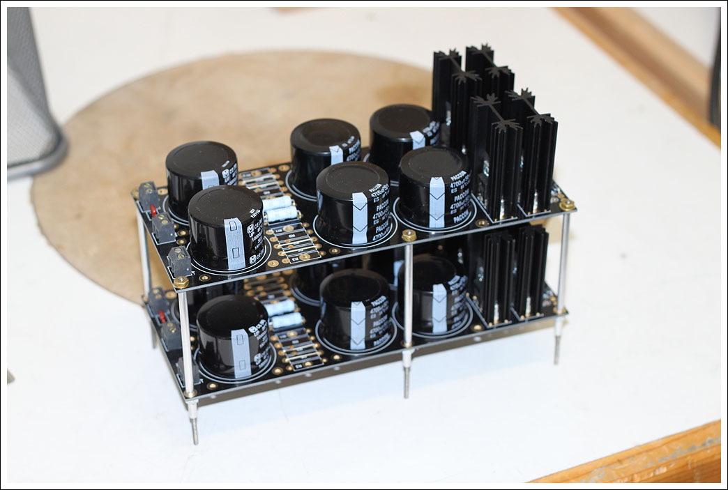
To save space the power supply boards are stacked using aluminum tube and 4-40 allthread as spacers. Cutting the rod to the proper lengths was pretty time consuming.
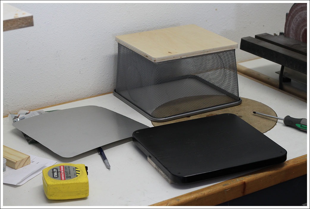
The bottom and top are pieces of decent plywood covered in aluminum flashing for shielding (pretty sure this is not UL approved).
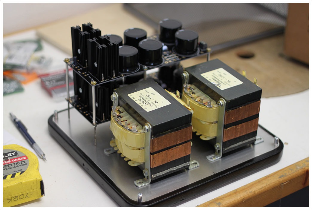
Here are the Signal transformers mounted to the chassis.
The cage fits over the whole thing and is centered using the four aluminum posts at the corners. It is clamped down by brackets on the sides.
All connections are through a thick aluminum plate from an old 12v power supply I had lying around.
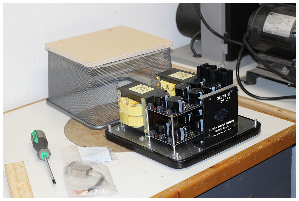
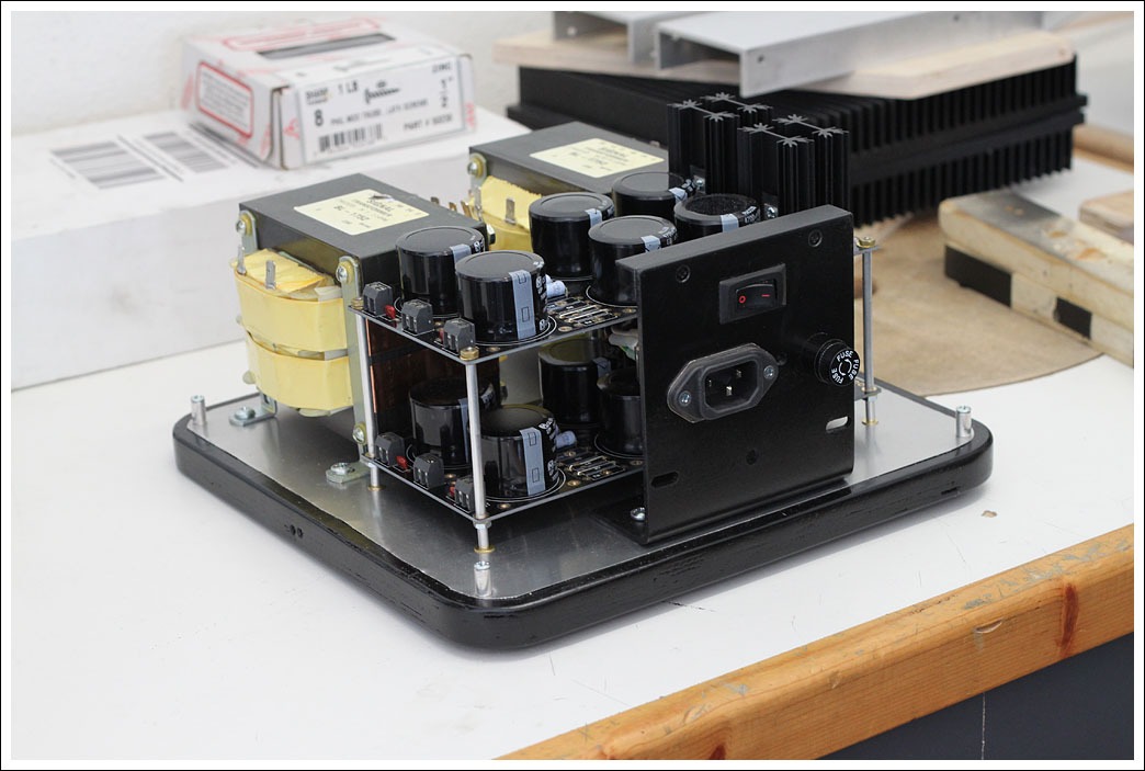
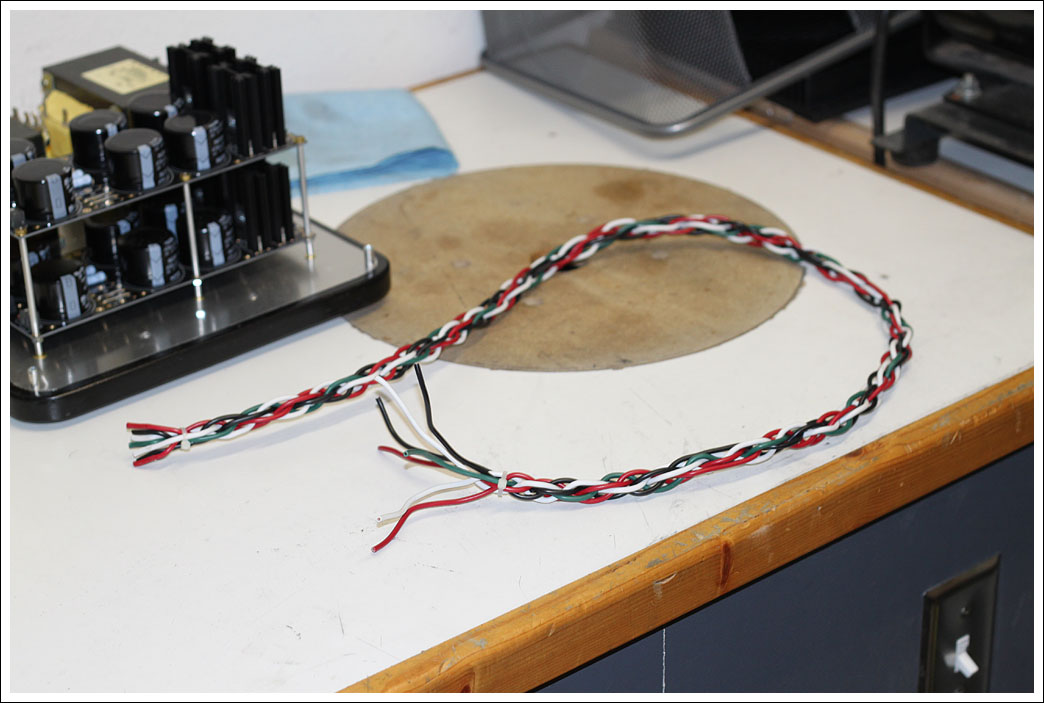
Power will run from the power supply to the amp through a 7 wire umbilical cord that I braided together.
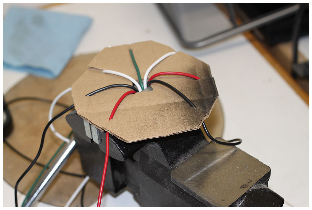
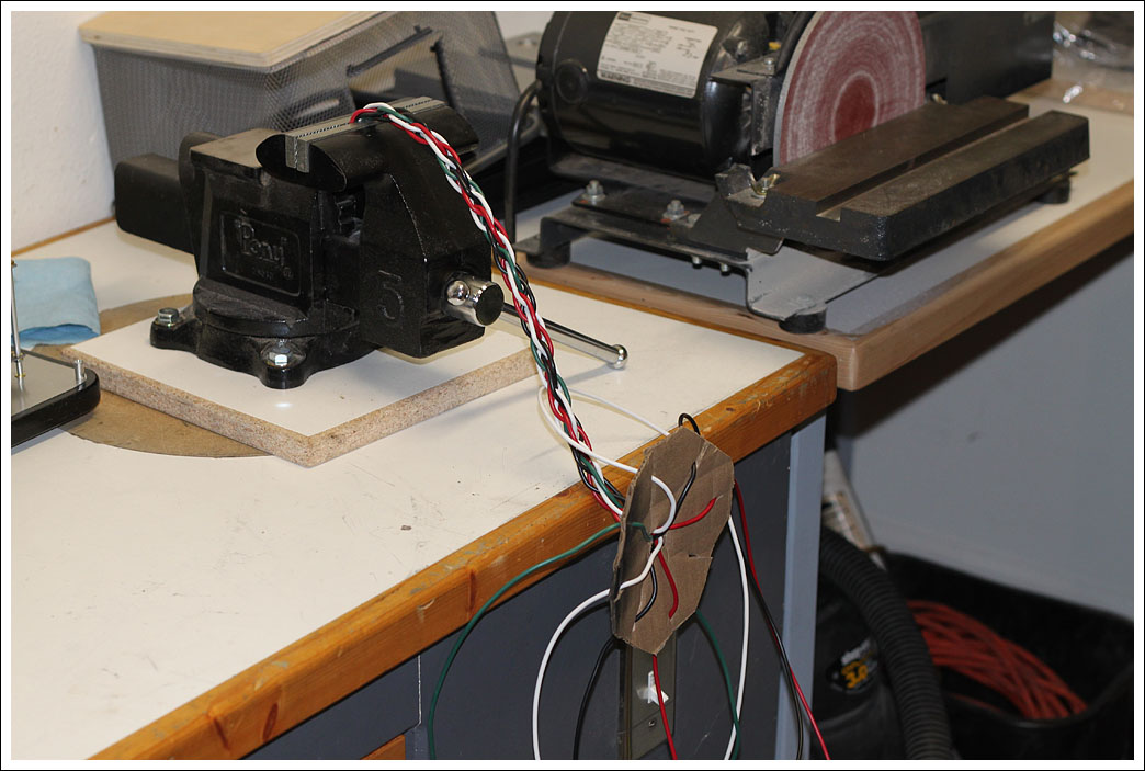
The wire is about 4' long so I have enough to locate the power supply the Pass approved minimum distance of 2' from the amp. The wire is 14g which should be fine for the relatively low currents involved.
- Matt
As with my Chipamps one of main components is an IKEA product, in this case a $5 garbage can. I needed a way to keep fingers out of the power supply, while still allowing for ventilation.
Abbreviated to to exactly proper height, give or take an inch or so.
Bending the edges, those are sharp and leave very nice cuts, and they are good for putting scrapes in your freshly painted parts.
The cage is about 6" tall.
To save space the power supply boards are stacked using aluminum tube and 4-40 allthread as spacers. Cutting the rod to the proper lengths was pretty time consuming.
The bottom and top are pieces of decent plywood covered in aluminum flashing for shielding (pretty sure this is not UL approved).
Here are the Signal transformers mounted to the chassis.
The cage fits over the whole thing and is centered using the four aluminum posts at the corners. It is clamped down by brackets on the sides.
All connections are through a thick aluminum plate from an old 12v power supply I had lying around.
Power will run from the power supply to the amp through a 7 wire umbilical cord that I braided together.
The wire is about 4' long so I have enough to locate the power supply the Pass approved minimum distance of 2' from the amp. The wire is 14g which should be fine for the relatively low currents involved.
- Matt
Last edited:
What a fantastic thread!!!!
I have some awesome, mil-spec connectors that you would be quite welcome to, but they are only 6-pin... I suppose you could run a separate screw lug for the ground, (similar to a phono ground) which would either look very cool or very bad, depending on execution. But your found-item engineering skills are fantastic, so you would probably make it look excellent!
I remember your Chipamp from Burning Amp, I thought it was supremely well done!
PM me if you want the connector, or more info.
What a fantastic thread!!!!
I have some awesome, mil-spec connectors that you would be quite welcome to, but they are only 6-pin... I suppose you could run a separate screw lug for the ground, (similar to a phono ground) which would either look very cool or very bad, depending on execution. But your found-item engineering skills are fantastic, so you would probably make it look excellent!
I remember your Chipamp from Burning Amp, I thought it was supremely well done!
PM me if you want the connector, or more info.
6L6,
That is very generous of you, you've got a PM. Thanks! 🙂
- Matt
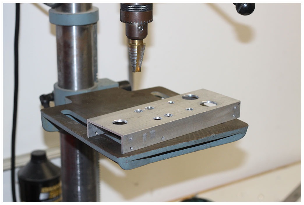
Here's some pictures of the amp chassis.
Drilling holes in the back panel.
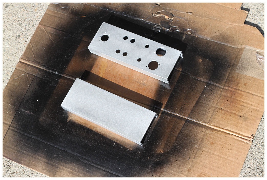
The ends are 3 1/2" c-channel that I textured and then clear coated.
Here's where a template of the amp boards comes in very handy.
Unfortunately I broke two different taps while tapping holes for the amp boards. On one (3mm) I was able to knock the tap out with a punch, on the other (6-32) the tap was stuck good and I had to drill a second hole. Arg. The amps are mounted on short plastic standoffs.
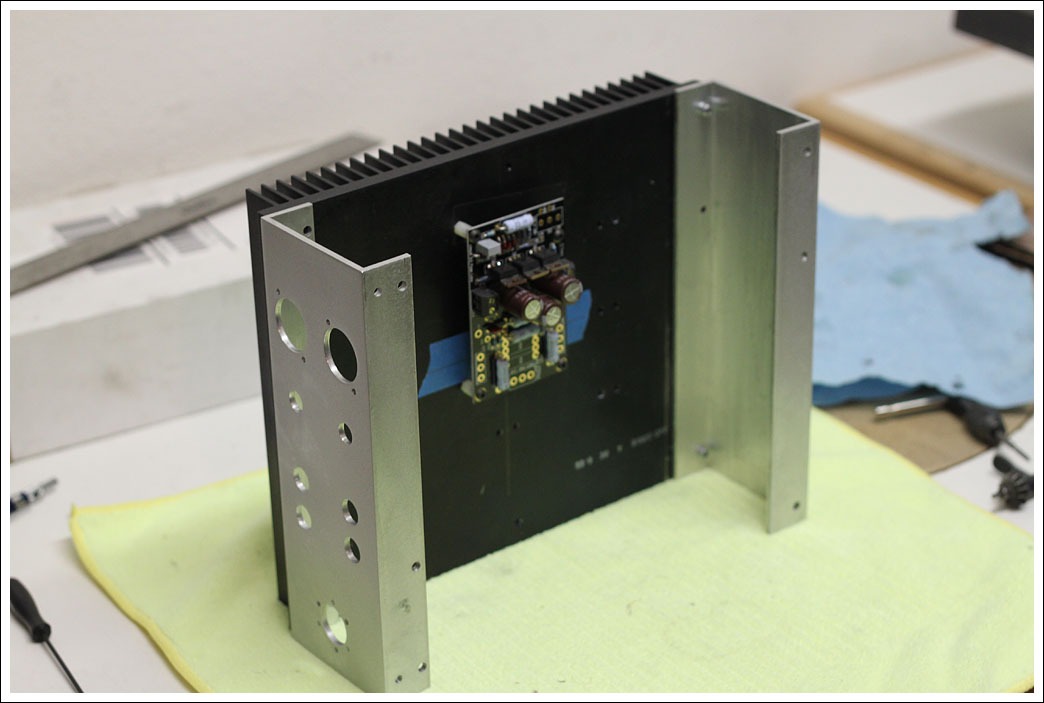
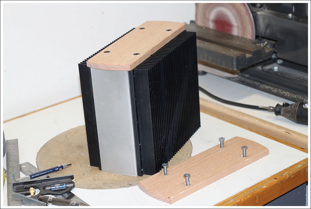
Test fitting with the ends in place. Thanks again to Variac for the c-channel.
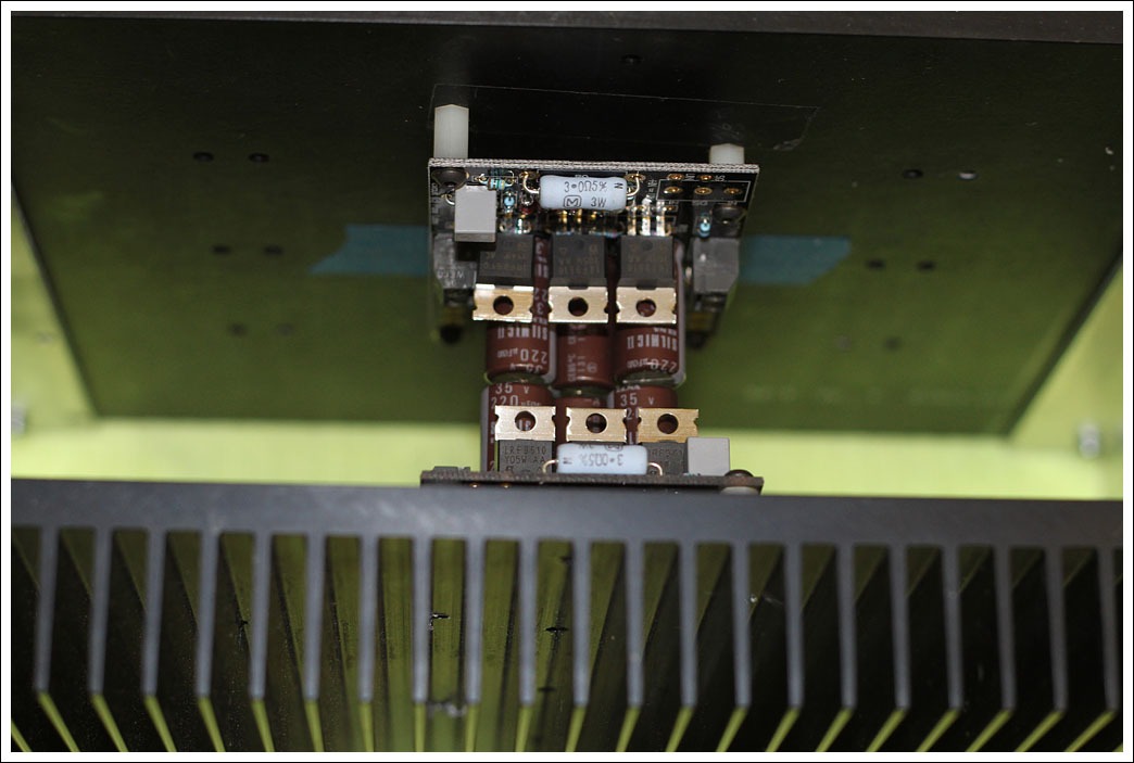
When assembled there is only about 3/16" clearance between the capacitors.
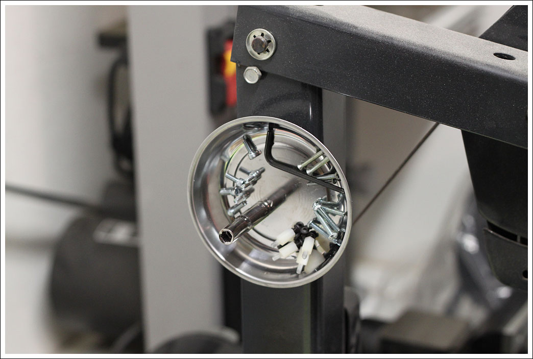
Various parts for the amps.
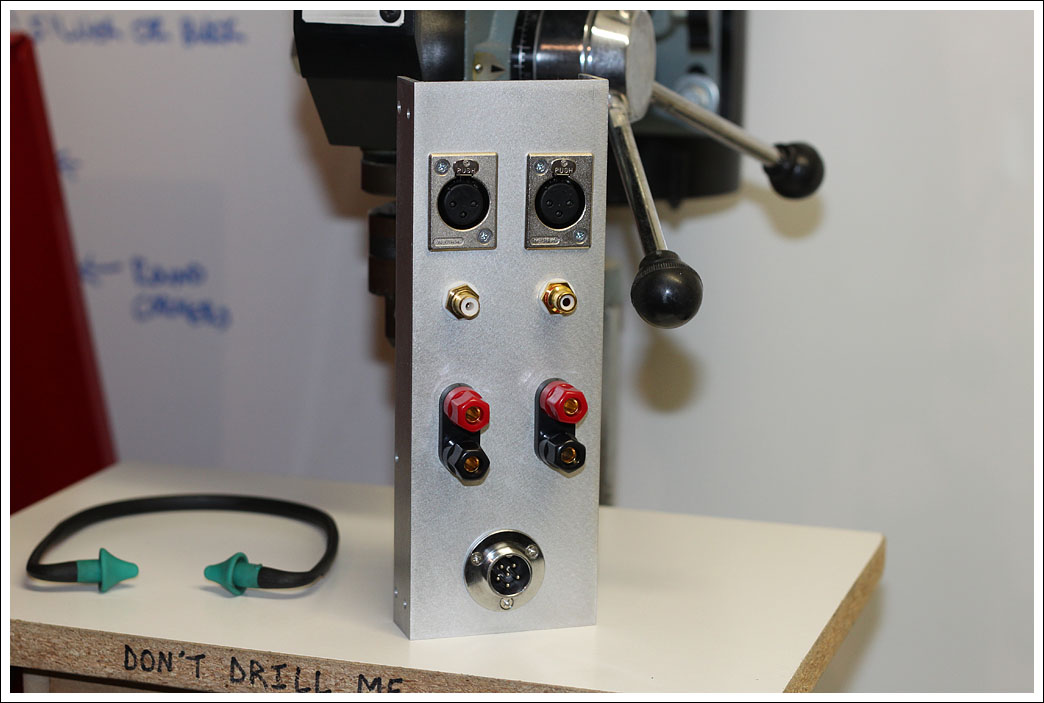
Test fitting the connectors on the rear panel. The power connector at the bottom is really small and most likely won't work out.
Amp with the sides attached.
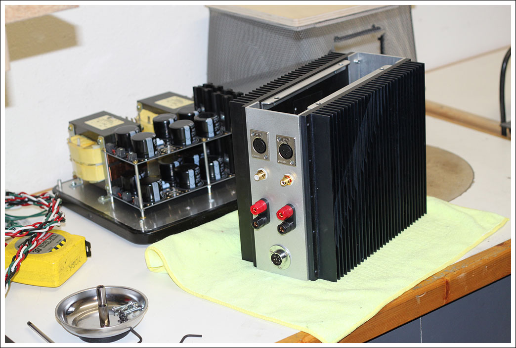
The top and bottom are 1/2" oak.
- Matt
Drilling holes in the back panel.
The ends are 3 1/2" c-channel that I textured and then clear coated.
Here's where a template of the amp boards comes in very handy.
Unfortunately I broke two different taps while tapping holes for the amp boards. On one (3mm) I was able to knock the tap out with a punch, on the other (6-32) the tap was stuck good and I had to drill a second hole. Arg. The amps are mounted on short plastic standoffs.
Test fitting with the ends in place. Thanks again to Variac for the c-channel.
When assembled there is only about 3/16" clearance between the capacitors.
Various parts for the amps.
Test fitting the connectors on the rear panel. The power connector at the bottom is really small and most likely won't work out.
Amp with the sides attached.
The top and bottom are 1/2" oak.
- Matt
Nicely done Matt, having an eye for mechanical elegance you get 5 stars.
Bill
Thank you for the kind words.
you need some holes on bottom and top plate ;
plenty of them .
Definitely, I'm just trying to decide on the layout. I think I'm going to go with 4 1.5" holes on each end.
- Matt
- Home
- Amplifiers
- Pass Labs
- Mini Aleph Build