As of this morning we have music! I managed to find some spare time over the last couple of weekends to work on the Aleph's. Last night I got on a roll and ended up working on them until 1am and was able to finish all of the wiring and then do initial testing to make sure the voltages were within the expected range. Under load my rails worked out to be roughly +/- 15.5v with the CRC resistors in place. The heatsinks barely get warm, so I should have more than enough thermal capacity, time to play with the bias? ")
This morning I was able to give them a quick listen and so far I'm quite impressed with the sound.
I have run into a couple of issues though, and would greatly appreciate suggestions.
1. There is a fairly significant "thump" on both turn on and turn off. This causes the speaker cones to move quite a bit, and I'm worried about damaging the tweeters. Is this to be expected?
2. I'm measuring about 50-60mV on the speaker terminals, which is leading to some hum. This could add to the turn on/off thump, but I'm assuming it is not the major cause. I will probably install some small potentiometers to tune out the offset.
3. There is only about 0.41v across the source resistors which works out to I=V/R=0.41/0.47=0.87A bias. This is lower than the target and can be adjusted by lowering the resistance of the source resistors or by adjusting R13. But... it seems to be a common problem with the Mini-A that bias current is lower than expected. I noticed post at one point saying that for the Mini-A R14 and R16 should be 750ohms instead of 1.5kohm as shown on the schematic. They look like a voltage divider to set the voltage of R13, but that wouldn't change in this case, but the voltage on Q5 would be effected. Any input on this?
4. The final issue is that I seem to have a loose connection or a cold solder joint somewhere on one of the inputs. One channel crackels in and out when the cable is moved, and I've tried a couple of cables they weren't bad. My setup is a bit complicated since I have the XLRs and RCAs with the negative input of the XLR currently grounded. I suspect one of these connectors is having a problem.
So, any input on the above is greatly appreciated. Here are some pictures of where the project is at.
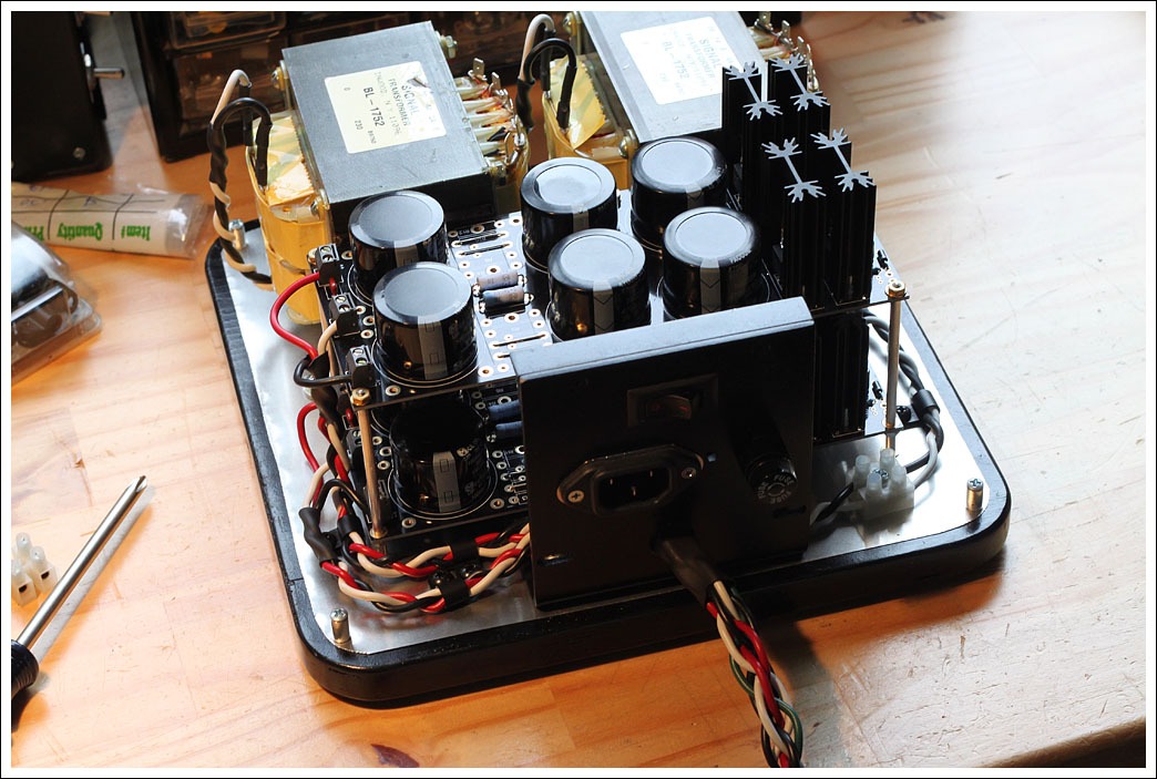
The power supply unit is about twice as big as the amp itself and is probably majorly overkill. Since this photo was taken I installed 20 2.7ohm resistors to implement a 29Hz CRC filter. The power cable now also has a strain relief.
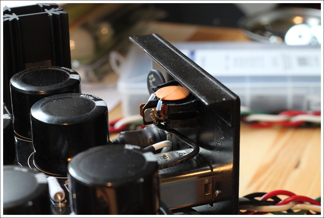
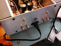
All 120v connections are point to point on the back panel. I put a small capacitor across the switch to prevent arcing, with a thermistor in series with the hot lead after that.
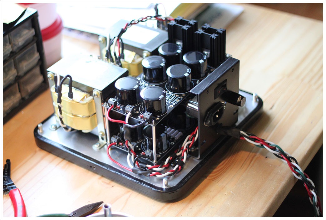
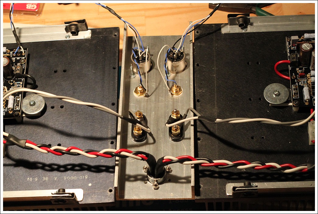
All AC lines are on this side of the unit. The 120v line is close to the ground for shielding. I'm pretty sick of braiding wire at this point.
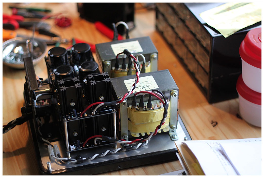
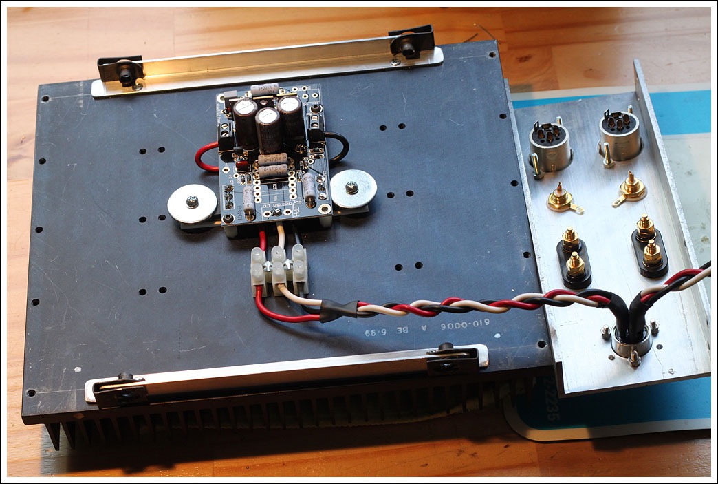
Here is the DC side of the unit. Unfortunately 6L6s connector was a bit too small for the 14g wire I used, but I have a plan for it in a future project. If I were building this again I would definitely go with 16g wire instead since it is easier to work with.
It was a very tight fit but I got all six 14g wires onto the power connector.
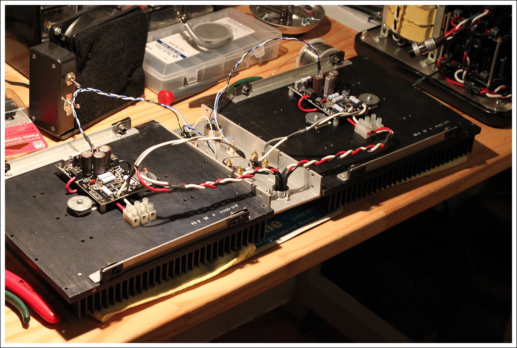
Here is one amp channel mounted on its heatsink. The mosfets are on aluminum oxide insulators.
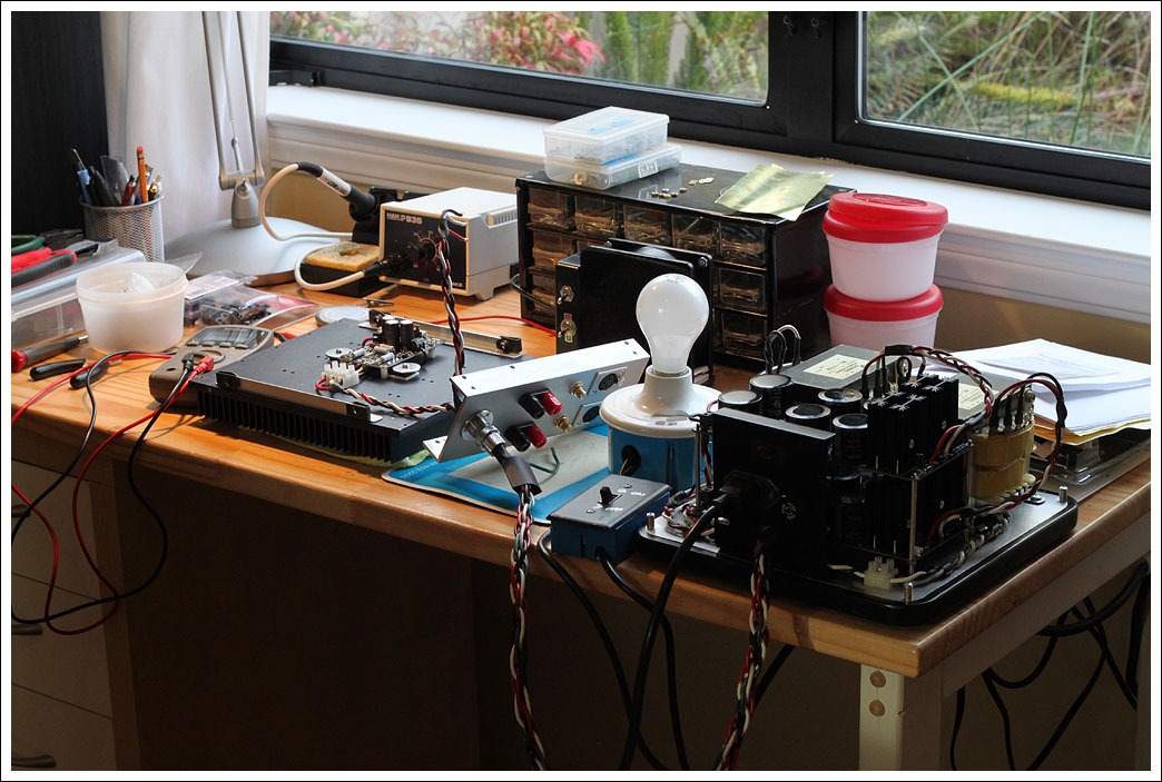
The setup for the initial power-on testing. Surprisingly, with the light bulb in series I only saw ~9v rails.
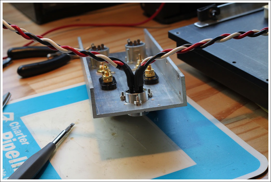
Here is the input panel wired up. Originally I was going to solder the speaker outputs to the binding posts, but could not get a good joint. Instead I crimped and soldered ring terminals on the wire, this should give a solid connection and is easy to disassemble. The signal wires are 22g cable from ApexJr, it is very nice but difficult to strip. Blue is positive, white is negative, and black is ground. As you can see the negative (white) is hooked to ground so I can use the RCAs. The loose connection is somewhere in this area.
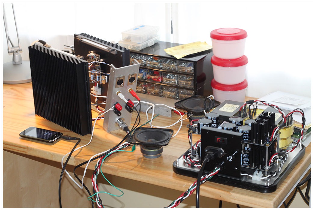
The amp all wired up and ready to play music, unfortunately it was 1am so that had to wait.
Testing with "no baffle" Pioneers 269-469s and an iphone as a temporary source.
- Matt
This morning I was able to give them a quick listen and so far I'm quite impressed with the sound.
I have run into a couple of issues though, and would greatly appreciate suggestions.
1. There is a fairly significant "thump" on both turn on and turn off. This causes the speaker cones to move quite a bit, and I'm worried about damaging the tweeters. Is this to be expected?
2. I'm measuring about 50-60mV on the speaker terminals, which is leading to some hum. This could add to the turn on/off thump, but I'm assuming it is not the major cause. I will probably install some small potentiometers to tune out the offset.
3. There is only about 0.41v across the source resistors which works out to I=V/R=0.41/0.47=0.87A bias. This is lower than the target and can be adjusted by lowering the resistance of the source resistors or by adjusting R13. But... it seems to be a common problem with the Mini-A that bias current is lower than expected. I noticed post at one point saying that for the Mini-A R14 and R16 should be 750ohms instead of 1.5kohm as shown on the schematic. They look like a voltage divider to set the voltage of R13, but that wouldn't change in this case, but the voltage on Q5 would be effected. Any input on this?
4. The final issue is that I seem to have a loose connection or a cold solder joint somewhere on one of the inputs. One channel crackels in and out when the cable is moved, and I've tried a couple of cables they weren't bad. My setup is a bit complicated since I have the XLRs and RCAs with the negative input of the XLR currently grounded. I suspect one of these connectors is having a problem.
So, any input on the above is greatly appreciated. Here are some pictures of where the project is at.
The power supply unit is about twice as big as the amp itself and is probably majorly overkill. Since this photo was taken I installed 20 2.7ohm resistors to implement a 29Hz CRC filter. The power cable now also has a strain relief.
All 120v connections are point to point on the back panel. I put a small capacitor across the switch to prevent arcing, with a thermistor in series with the hot lead after that.
All AC lines are on this side of the unit. The 120v line is close to the ground for shielding. I'm pretty sick of braiding wire at this point.
Here is the DC side of the unit. Unfortunately 6L6s connector was a bit too small for the 14g wire I used, but I have a plan for it in a future project. If I were building this again I would definitely go with 16g wire instead since it is easier to work with.
It was a very tight fit but I got all six 14g wires onto the power connector.
Here is one amp channel mounted on its heatsink. The mosfets are on aluminum oxide insulators.
The setup for the initial power-on testing. Surprisingly, with the light bulb in series I only saw ~9v rails.
Here is the input panel wired up. Originally I was going to solder the speaker outputs to the binding posts, but could not get a good joint. Instead I crimped and soldered ring terminals on the wire, this should give a solid connection and is easy to disassemble. The signal wires are 22g cable from ApexJr, it is very nice but difficult to strip. Blue is positive, white is negative, and black is ground. As you can see the negative (white) is hooked to ground so I can use the RCAs. The loose connection is somewhere in this area.
The amp all wired up and ready to play music, unfortunately it was 1am so that had to wait.
Testing with "no baffle" Pioneers 269-469s and an iphone as a temporary source.
- Matt
This was a great project!
I've just finished my build as well, and I notice a small turn on and turn off thump.....not even a thump really, I just see the cones move (FR Fostex 207E). I have 66K per rail is the PS with a pair of CL-140 ICLs, not sure if that has any impact on thumping.
I built it per the excel spreadsheet as well with 750 ohm at R12 and .47 ohm source R's and R13 at 47K.
The bias was a bit low as you noted, IIRC about .8A bias. The sine waves on my scope had almost a "crossover-ish" distortion characteristic to them (and a few other anomalies) when I cranked up the input from my generator. My DC offsets were about 25 and 45 mV. I've already installed a 500 trimmer for DC offset (works great, takes a bit of time to settle when adjusting) and upped R13 to 150K. Sine waves look much cleaner and I'm getting about 9.8W at clipping with B+ at about 13.5V and bias current at a little over an amp. The DC offsets are both now around 2mv when dialed in with the trimmer pot. Cranking the bias made a very noticeable difference in sound quality; I'd consider cranking it up further, as my heat sink temps are reasonable, but my transformers may be a little undersized (two separate 12V @ 70VA each).
Attachments
Last edited:
Do you have a star ground ?
The amp is setup as two monoblocks in a shared enclosure, so the only electrical connection between the two channels is the chassis ground. For each channel the power supply DC ground goes straight to the amp board, and then the grounds for the input and output are also connected to the board, so you could consider the ground plane on the board as the "star ground" for each channel. I currently have no connection between the DC grounds and the chassis ground.
I've just finished my build as well, and I notice a small turn on and turn off thump.....not even a thump really, I just see the cones move (FR Fostex 207E). I have 66K per rail is the PS with a pair of CL-140 ICLs, not sure if that has any impact on thumping.
I built it per the excel spreadsheet as well with 750 ohm at R12 and .47 ohm source R's and R13 at 47K.
The bias was a bit low as you noted, IIRC about .8A bias. The sine waves on my scope had almost a "crossover-ish" distortion characteristic to them (and a few other anomalies) when I cranked up the input from my generator. My DC offsets were about 25 and 45 mV. I've already installed a 500 trimmer for DC offset (works great, takes a bit of time to settle when adjusting) and upped R13 to 150K. Sine waves look much cleaner and I'm getting about 9.8W at clipping with B+ at about 13.5V and bias current at a little over an amp. The DC offsets are both now around 2mv when dialed in with the trimmer pot. Cranking the bias made a very noticeable difference in sound quality; I'd consider cranking it up further, as my heat sink temps are reasonable, but my transformers may be a little undersized (two separate 12V @ 70VA each).
Very nice build! I experience the same slow cone movement on power on and off, there is no audible noise. It is interesting that several of us saw ~.8A bias using the stock values, this is why I'm wondering if perhaps something is slightly off. It's good to hear that the sound quality improved with the higher bias, hopefully I can find time in the next week or so to adjust my trim pots and get everything in spec.
The Signal BL1752 transformers I used are $8 at ApexJr. The rails were ~18v with no load, and fall to ~15.5v with load. According to the power spreadsheet if I run 1.4A rails this should be good for 10w @ 8ohm and 16w @ 4ohm.
- Matt
I have mine wired with the out and ground on Brian's board going to insulated binding posts, and the Cground (Chassis ground I assume) wired to the ground on the power supply board; the power supply ground is then tied to the chassis ground along with the ground conductor from the power entry (star ground).
My RCA inputs are also insulated with the coax shield connected at both the RCA and the PCB.
I have a miniscule amount of hum (shows up as some fuzz around 0V with the scope set at 5mv) that I haven't yet noticed on my 95db speaks.
My RCA inputs are also insulated with the coax shield connected at both the RCA and the PCB.
I have a miniscule amount of hum (shows up as some fuzz around 0V with the scope set at 5mv) that I haven't yet noticed on my 95db speaks.
I have mine wired with the out and ground on Brian's board going to insulated binding posts, and the Cground (Chassis ground I assume) wired to the ground on the power supply board; the power supply ground is then tied to the chassis ground along with the ground conductor from the power entry (star ground).
My RCA inputs are also insulated with the coax shield connected at both the RCA and the PCB.
I have a miniscule amount of hum (shows up as some fuzz around 0V with the scope set at 5mv) that I haven't yet noticed on my 95db speaks.
Brian's board has the signal output ground and the cground tied together. Am I correctly understanding that you have your power supply ground tied to cground on the board and also to the chassis itself? This would mean that the center taps on your transformers are tied together correct?
Boywonder,
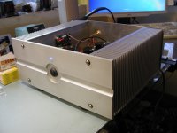
Outstanding metal work! Did you do it yourself? I can see some elements of style similar to you Poindexter Music Machine build.
Thanks! Yes, fabbed in the garage. The heat sinks are Antek/Par-Metal HS11XX series, 5" tall, the rest is fabbed from aluminum rems from the local metal supplier. Transformers and bridge rectifiers are leftovers from an old work project.
I got lazy on the binding posts when I found shouldered nylon washers from McMaster to isolate the posts from the chassis, no exotic wood insert.....
I'm considering anodizing it.....perhaps when I get the next project built (F4 is next), I'll get the whole lot anodized to save $$ on the minimum fee.
Attachments
Last edited:
Brian's board has the signal output ground and the cground tied together. Am I correctly understanding that you have your power supply ground tied to cground on the board and also to the chassis itself? This would mean that the center taps on your transformers are tied together correct?
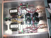
Correct. The two grounds are tied together on Brian's PCB and one goes to the binding post and the other to the PS ground, then PS ground to chassis ground stud. My transformers are single 12V secondaries; one is doing the -ive rail and the other is doing the +ive rail, no center taps.
Correct. The two grounds are tied together on Brian's PCB and one goes to the binding post and the other to the PS ground, then PS ground to chassis ground stud. My transformers are single 12V secondaries; one is doing the -ive rail and the other is doing the +ive rail, no center taps.
Ah gotcha, I didn't notice in picture that you were using two transformers to get the +/- rails, I assumed they were center tapped.
So tell us how it sounds compared to toobz!
I gave it a good listen last night, and it's quite nice. Good imaging, slightly hot/sibilant on the highs...very slight, at least compared to my TubeLabSE 300B. Plenty of power for 95db speakers. Barely any audible hum if you stick your ear next to the cones, at least as low as my tube stuff. I have noticed that the transformers hum very slightly.
I'm running generic 50V bridge rectifiers so I'll probably try some schottky's or FREDs and see if I can get an improvement.
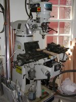
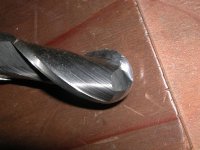
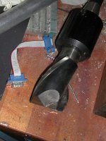
How did you machine that groove in the faceplate? You said you did it at home?
With a Bridgeport, a ball end mill and a big-*** 2 flute end mill.......... (not counting the mounting holes, just a drill bit for those)...
Attachments
I've installed precision potentiometers in place of R8 to adjust the DC offset and R13 to adjust the bias.
Using R13 I am able to get the bias up to ~1.17v (.550v across .47ohm source resistor) but it won't go any higher than that. This again makes me wonder if R14 and R16 should be 750ohm for the Mini-Aleph.
The DC offset on each channel started out around 70mV, by adjusting R8 I've lowered it to < 10mV on each channel. What is interesting is that each time R8 is adjusted the offset fluctuates wildly and then slowly returns back to close to the original value. It took some fairly large resistance changes to get it stable at < 10mV.
So far I am very impressed with the sound quality. Compared to other amps I own it is if there is a layer of "fuzz" removed that was masking the real signal. Interestingly enough our cats now give the speakers confused looks when they are playing, apparently because they can't locate the source of the sound. They haven't done this with other amp setups, so either the sound is more realistic or possibly the amp is putting out some super-sonic noise that is driving them nuts. The amp is making my speakers faults more noticeable, so in the true DIY audio cycle my next project will likely be a new set of speakers.
The next steps are to finish the enclosures so that the amps and power supply are shielded, currently there is a bit of hiss which I hope goes away when this is done. I also have a set of Vishay MKP capacitors that I'm going to use to bypass C1/C2/C3 to see if that makes difference.
- Matt
Nice! Are you going to post a few pics of the finished product?
My bias seems very close to yours IIRC, although I did not try to take it any higher. So if you leave R13 disconnected there is not much increase in bias? My heat sinks get quite warm but I can touch my hand on them indefinitely.
My bias seems very close to yours IIRC, although I did not try to take it any higher. So if you leave R13 disconnected there is not much increase in bias? My heat sinks get quite warm but I can touch my hand on them indefinitely.
Nice! Are you going to post a few pics of the finished product?
My bias seems very close to yours IIRC, although I did not try to take it any higher. So if you leave R13 disconnected there is not much increase in bias? My heat sinks get quite warm but I can touch my hand on them indefinitely.
Definitely, once I do final assembly I'll upload some more pictures. I'm still trying to figure out why the bias maxes out at ~1.17A (not 1.17v as I mistyped previously). My heat sinks are warm but not hot, and I think I could safely run 1.2-1.3A. One option is to lower the resistance of the source and sense resistors, but I'm hesitant to desolder and replace them.
- Matt
- Status
- This old topic is closed. If you want to reopen this topic, contact a moderator using the "Report Post" button.
- Home
- Amplifiers
- Pass Labs
- Mini Aleph Build