Folks:
The power supplies in both of my F5T V3 monoblock amps are sporting 160,000 uF, consistent with Nelson's F5T design. The amps sound terrific, but slightly "thinner" than the Pass Labs Aleph 1.2 monoblocks they superseded.
What boards are you using and what AWG wire have you used in linking them up?
bashbap:
The power supply pcbs were sourced from Buzzforb, who had a small number built to accommodate the parts sold under his first F5T group buy. The boards are large and, to my untrained eye, well-designed. Each board is just large enough to support the sixteen 35mm diameter 10,000 uF Nichicon KG caps that Buzz supplied. The wire I'm using for the power runs in the amp is 14 gauge stranded THHN; far more exotic wire is being used for the audio lines (let the derision begin).
6L6 and Vince:
Understood. I don't have any equipment (other than multimeters) that would allow me to calibrate the effects of twirling P3, so I guess I'll need to just rely on my ears. Fortunately, Vince lives nearby, so I may be able to prevail upon him to help me.
dazed2:
The rail voltages on my V3 monoblocks hover around +/-44VDC. I also built two stereo F5T V2 amps for friends; one of those also has +/-44VDC rail voltages and the other has rail voltages around +/-33VDC.
As always, thanks for the advice!
Regards,
Scott
so I guess I'll need to just rely on my ears. Fortunately, Vince lives nearby, so I may be able to prevail upon him to help me.
You can certainly try by ear, but it's best done visually (spectrum analyzer) and by listening. You could wind up with an imbalance between channels. Then, you'll just have to try and center the pots again. Although the P3 adjustment is a bit easier than the two pot adjustment on the F6.
 You'd have to adjust, then listen, adjust then listen, etc.
I'll try to build the analyzer probe in a small box and then you can install a spectrum analyzer app of your choice on your laptop. The laptop needs to have a decent audio card. I forget the specs it needs.
Regards,
Vince
Last edited:
bashbap:
The power supply pcbs were sourced from Buzzforb, who had a small number built to accommodate the parts sold under his first F5T group buy. The boards are large and, to my untrained eye, well-designed. Each board is just large enough to support the sixteen 35mm diameter 10,000 uF Nichicon KG caps that Buzz supplied. The wire I'm using for the power runs in the amp is 14 gauge stranded THHN; far more exotic wire is being used for the audio lines (let the derision begin).
Scott I meant; did you use the store boards FE and output boards and the AWG wire connecting them. What AWG wire did you use for the output speaker connection + and _. In my opinion that will definitely effect the sound.
Nash
Nash:
Yes, I used the diyAudio store boards. The power connections going to the F5T boards were the same 14 gauge stranded THHN. The input and output connections to the F5T boards were made using Neotech 24 gauge solid Teflon-insulated UPOCC copper wire and Neotech 14 gauge stranded Teflon-insulated UPOCC copper wire, respectively.
Regards,
Scott
SRMcGee :
So in terms of energy. you are going from about 154J or storage to 242J of storage. Or about 50% more.
Yes you will get better bass response.
To compare, in the one I built, I am running 50V rails, which in my case equates to 705J of energy per monoblock. Absolutely no problem with deep deep bass and is able to control 2x 10" bass drivers with a bunch of midranges and tweets (5+2 in all) with no problem.
If you add more caps, I wouldn't both with the "R" in the RC just wire them up after the initial RC that you have already and you will be fine.
Or to make life easier, instead of using those 10KuF caps, swap them out for 22KuF. Just be careful with the soft start circuit. The extra capacitance may blow your fuses. A slow charge circuit may be necessary.
So in terms of energy. you are going from about 154J or storage to 242J of storage. Or about 50% more.
Yes you will get better bass response.
To compare, in the one I built, I am running 50V rails, which in my case equates to 705J of energy per monoblock. Absolutely no problem with deep deep bass and is able to control 2x 10" bass drivers with a bunch of midranges and tweets (5+2 in all) with no problem.
If you add more caps, I wouldn't both with the "R" in the RC just wire them up after the initial RC that you have already and you will be fine.
Or to make life easier, instead of using those 10KuF caps, swap them out for 22KuF
. Just be careful with the soft start circuit. The extra capacitance may blow your fuses. A slow charge circuit may be necessary.Problem with new version F5-T boards
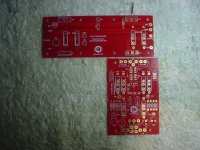
I received my DIY store boards yesterday. These are the latest version.
I find that I can barely insert a 18AWG stranded wire into the V+, V_, G, O/P and Gate holes. Looks like they have drilled these holes smaller than on the previous version since both you and Dazed2 have reported that they fitted larger diameter wire thru them. The hole size is 1.2mm which is inadequately small. The wire holes are actually smaller than the Mosfet (Q4 in the pic) holes (1.6mm) and the test point holes. The small piece of wire in the pic is 14AWG solid wire for reference. This just fits in the Mosfet holes. Doesn't make sense to me.
To illustrate my point further, take a look at the store F-5 clone boards. The V+, V- and Output holes are larger than the Mosfet Q3, Q4 mounting holes and appear to be around 2.0mm. This is the way it should be.
Has anyone else received the latest version of the store boards and has the same issue? Are these boards defective?
Nash
Nash:
Yes, I used the diyAudio store boards. The power connections going to the F5T boards were the same 14 gauge stranded THHN. The input and output connections to the F5T boards were made using Neotech 24 gauge solid Teflon-insulated UPOCC copper wire and Neotech 14 gauge stranded Teflon-insulated UPOCC copper wire, respectively.
Regards,
Scott
I received my DIY store boards yesterday. These are the latest version.
I find that I can barely insert a 18AWG stranded wire into the V+, V_, G, O/P and Gate holes. Looks like they have drilled these holes smaller than on the previous version since both you and Dazed2 have reported that they fitted larger diameter wire thru them. The hole size is 1.2mm which is inadequately small. The wire holes are actually smaller than the Mosfet (Q4 in the pic) holes (1.6mm) and the test point holes. The small piece of wire in the pic is 14AWG solid wire for reference. This just fits in the Mosfet holes. Doesn't make sense to me.
To illustrate my point further, take a look at the store F-5 clone boards. The V+, V- and Output holes are larger than the Mosfet Q3, Q4 mounting holes and appear to be around 2.0mm. This is the way it should be.
Has anyone else received the latest version of the store boards and has the same issue? Are these boards defective?
Nash
Attachments
Good afternoon,
I am looking for some input regarding a soft start circuit I made for my F5 turbo V2. I have 15 ohms of resistance on each AC line (running dual mono). The switch works fine but I have an issue as soon as the relay closes to switch the AC directly in line with the toroid. I have a capacitance multiplier on the PSU to help kill all the ripple. I have about 80,000uf of capacitance on each channel. I'm running with a single 60V rail per channel and set up the amp with a 30V "ground". As such I am running with a large output capacitor. The output cap is a nichion super through 22,000uf.
My issue is when I have a scope probe on the PSU output and another on the speaker side of the output coupling capacitor I see a really odd behaviour at start up. With the variac at 75% I have no issues but with the variac at full power I get a nice smooth curve as the voltage ramps up on the PSU but when the relay switches the line directly to the toroid I get a massive amount of sharp voltage spikes on the output. I always shut down the supply before anything bad happens.
Any ideas where this large spikes are coming from after the output capacitor. Any help would be much appreciated.
Cheers.
Nash:
I suspect the hole sizes on the new F5T pcbs are the same as the version I used. To make a good connection using stranded 14 gauge wire, I cut away just enough of the strands to allow those that would fit through the holes to do so. The strands that were cut shorter were all cut to the same length, so they ended up "kissing" the top surface of the solder pad. I soldered the longer strands on the rear side of the pcb and added solder on the top side as well, so the shorter strands would be contained and connected to the solder pad.
Regards,
Scott
Nash:
I suspect the hole sizes on the new F5T pcbs are the same as the version I used. To make a good connection using stranded 14 gauge wire, I cut away just enough of the strands to allow those that would fit through the holes to do so. The strands that were cut shorter were all cut to the same length, so they ended up "kissing" the top surface of the solder pad. I soldered the longer strands on the rear side of the pcb and added solder on the top side as well, so the shorter strands would be contained and connected to the solder pad.
Regards,
Scott
Scott,
If you look at pics of the older version and the latest you can clearly see the reduction in hole size. In the version I believe you used, you could easily get 16AWG stranded wire in and with some trimming a 14AWG stranded as you have done. If this is incorrect please let me know. What is the version # silkscreened on your boards? In the latest version you can just about get a 18AWG stranded in. That is the problem. Otherwise the boards look good.
Any luck sorting out the "thinness" in sound you complained about?
Nash (Southern NJ)
hello folks
have some problems with my F5Turbo
having problems with offset and started to measure bias at the different 1R pairs by the output devices
Across PNP side
R17 and R18 365mV
R19 and R20 352mV
Across NPN side
R21 and R22 368mV
R23 and R24 344mV
Offset approx 5mV
Is this sign of badly matched output transistors or normal?
best
Leif
Your bias readings are actually quite good - remember you are comparing N and P channel devices.
If your offset is stable at 0.005V (5mV) it's set very well!!
Is there any offset drift once the amplifier is power on for 45-60 minutes? If no, you are done. Connect speakers and enjoy!
If your offset is stable at 0.005V (5mV) it's set very well!!
Is there any offset drift once the amplifier is power on for 45-60 minutes? If no, you are done. Connect speakers and enjoy!
it takes close to an hour to reach thermal stability and these bias readings
but what about the difference within the PNP and NPN devices?
aren´t they too big?
don´t like that offset starts way ahead (about 90mV) and creaps slowly down
not good for compression drivers (TAD4001 and 2001)
approx 33vdc supplied from choke input supply and 1kva 40vac powertransformer
best
Leif
but what about the difference within the PNP and NPN devices?
aren´t they too big?
don´t like that offset starts way ahead (about 90mV) and creaps slowly down
not good for compression drivers (TAD4001 and 2001)
approx 33vdc supplied from choke input supply and 1kva 40vac powertransformer
best
Leif
it takes close to an hour to reach thermal stability and these bias readings
That's about normal, the big amos take a while to get to thermal stability.
but what about the difference within the PNP and NPN devices?
aren´t they too big?
No. In fact, your devices are quite close.
Anyway, the N and P Vgs rarely, if ever, matchdon´t like that offset starts way ahead (about 90mV) and creeps slowly down
not good for compression drivers (TAD4001 and 2001)
... that's part of it being an F5. You may want to install a relay or switch on the output if you are concerned.
I apologize in advance for being such a noob. I have been doing research and have read about 300 pages of this thread and am still confused on a bunch of things.
I was planning on building F5T V2 or V3 monoblocks, but am not sure which one is better suited for my needs. I am looking to get 100W class A into 8ohms.
First of all the Mosfets. The recommended FQA12P20/FQA19N20 seem to be very hard to find unless you want to risk buying them from china. Does anyone know where to source these? Then there are the Toshiba offerings (2SK1530/2SJ201) which because of their lower current ratings may or may not work, but are also very hard to find. Finally the ones that are still in production seem to be the FQP12P20/FQP19N20, IRFP9240/IRFP240. Which is recommended?
Use the IRFP240/9240 The factory-build Pass amps are using them. If they are good enough for Papa, they are good enough for me.
You say you need 100W into 8R...
What kind of speakers do you have, how big is the room, what kind of music do you listen to, and (be honest) how loud do you like it?
And can your room deal with the heat from an amp that big?
You say you need 100W into 8R...
What kind of speakers do you have, how big is the room, what kind of music do you listen to, and (be honest) how loud do you like it?
And can your room deal with the heat from an amp that big?
- Home
- Amplifiers
- Pass Labs
- F5 Turbo Builders Thread