This has been asked before (no doubt) but I can take the verbal abuse for asking now.
Is there a recommended TX or 2, and is there a BOM yet?
Mark,
Thanks for posting pictures and update, with the kind offer of pre-sales. I'll wait until it is a known, non bug, non typo set of boards. I don't need any handicaps to help me screw up the build.
Merry Christmas
Yeah, they look green to me as well. >50 eyes?
Ron
Kinda looks red and green on my monitor too.
It's red and gold though. So at the moment the plan is to wait to put them in the store until one of the test builders has an operating channel. That's the prudent thing.
If anyone thinks they can get it built really quickly, ie they have the parts, and want to take a chance and order now then they should contact me.
Mark

Hi all,
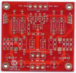
I've got some of the new F5t boards in hand. I'm planning on going V2 monoblocks.
I've got two 25 volt 500 VA transformers I'll be using and some big screw top caps.
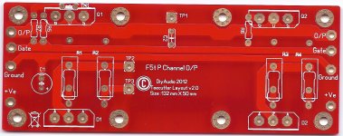
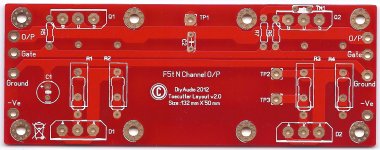
Something I can't seem to find is a list for populating the boards in the V2 style. What components are omitted, what needs jumpers, and what parts on Pass' published schematic correspond to part numbers on the board.
The issue is the part numbers on the board don't correspond to the part numbers in the schematic. I've started a spread sheet to straighten things out that I will post. Any help I could get on this would be great.
Best,
Nelson
I've got some of the new F5t boards in hand. I'm planning on going V2 monoblocks.
I've got two 25 volt 500 VA transformers I'll be using and some big screw top caps.
Something I can't seem to find is a list for populating the boards in the V2 style. What components are omitted, what needs jumpers, and what parts on Pass' published schematic correspond to part numbers on the board.
The issue is the part numbers on the board don't correspond to the part numbers in the schematic. I've started a spread sheet to straighten things out that I will post. Any help I could get on this would be great.
Best,
Nelson
Attachments
it say v2.0it was the sec board layout.
Ding ding
I forgot to add my spreadsheet of the parts population. I seem to have it all worked out but the more who check the better off we'll be. I'm not sure about jumpers but I kinda think they won't be needed. I'll have to trace out the board in more detail later.
I am not planning on cascoding, my rails will be right around 32 volts which should be fine for the input jfets.
Here's the list.
https://docs.google.com/open?id=0B5APPDyzdf2pMF9wOS16ZFpEOVk
The forum doesn't take .xlsx (excel) files. If you want the original there's a .zip attached.
Best,
Nelson
Attachments
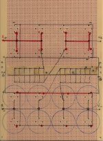
it is for linking the midpoint of R3 and 4 to ground. as far as i know, it was made as a link for a reason regarding balanced version. so you need to make a link there
EDIT: after a quick check, i see that i was right in balanced version, the midpoint of R3 and 4 are conected to the midpoint of R3 and 4 of ampboard nr2 and not to ground.
EDIT: after a quick check, i see that i was right
in balanced version, the midpoint of R3 and 4 are conected to the midpoint of R3 and 4 of ampboard nr2 and not to ground.
Last edited:
- Status
- This old topic is closed. If you want to reopen this topic, contact a moderator using the "Report Post" button.
- Home
- Amplifiers
- Pass Labs
- F5 Turbo Circuit Boards