Because my power transfomer output have daul AC 35-0-35, So hwen i apply to F5 circuit, after regulator, DC have +- 48V , so how can i do?you can't have +- AC voltages.
what do you actually have?
A DC, or dual polarity DC, or AC, or dual AC?
That's better, Now you make sense.
I shall re-state and you can tell us if that is correct.
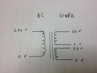
Transformer is 800VA 35 +35Vac
Rectified output on your mains supply is +-48Vdc when on zero load (open circuit).
Or, you have a two channel regulator to bring the voltage down to 48Vdc?
The F5 runs on +-25Vdc
I shall re-state and you can tell us if that is correct.
Transformer is 800VA 35 +35Vac
Rectified output on your mains supply is +-48Vdc when on zero load (open circuit).
Or, you have a two channel regulator to bring the voltage down to 48Vdc?
The F5 runs on +-25Vdc
Last edited:

Yes you can, but you will either need large sinks or lower output bias. Its all about implementation.
Could you draw a circuit for this implement?
Let me know what components I need to buy.
Thank you.
Could you draw a circuit for this implement
Nelson Pass has already done this -- you should build an F5turbo v3
http://www.firstwatt.com/pdf/art_f5_turbo.pdf
The voltage of your transformer will prove to be no problem.
Nelson Pass has already done this -- you should build an F5turbo v3
http://www.firstwatt.com/pdf/art_f5_turbo.pdf
The voltage of your transformer will prove to be no problem.
Thx. I will made F5 turbo V3.
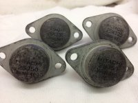
Other things, Could i use Hitachi 2SK135/2SJ50 to replace FQA12P20/FQA19P20 ?
On my hand have 12 pcs per each Hitachi FET
Attachments
Hi Everyone,
Hope I'm not bringing up a sore subject, but how are the F5T boards coming along?
Any plans for mono block boards?
Also, if you were to make a F5T board for mono blocks, how would boards be configured?
For instance, if you are using a standard case with heat sinks on each side, how would the boards be configured? Would you use an input/driver board attached to the base plate and feed power and signal to output boards via wire or a single board spanning the space betweem heat sinks? One board would lock you into a particular sized case, right?
Thanks,
Vince
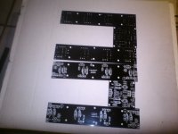
those are (allmost) the boards that will come in the store.
as far as i know, the output boards will be split in 2.
this is the UKToecutter's prototype turbo V3 boards.
I thought you were going to build and give feedback ...? what ever happened to toeC ?
Knowing what i know now i should have taken those boards from Toe ,,,
- Status
- This old topic is closed. If you want to reopen this topic, contact a moderator using the "Report Post" button.
- Home
- Amplifiers
- Pass Labs
- F5 Turbo Circuit Boards