Hi folks,
Would you all be interested in yet another F5 build thread? I'm in the middle of collecting parts right now but would be happy to share my progress if there's interest in more DIY amp pr0n! 😀
Would you all be interested in yet another F5 build thread? I'm in the middle of collecting parts right now but would be happy to share my progress if there's interest in more DIY amp pr0n! 😀
No pictures yet... but here's where I'm sourcing parts from so far:
PSU parts:
Mouser Project: link to misc parts
ebay PCB: link (sorry... didn't hear from Pete for a week so I assumed the "real" boards weren't available anymore)
Trafo: Got the shielded one from Antek: AS4218
Heat Sinks:
Got the ones that Antek uses for this enclosure. $25 each shipped with the trafo to help minimize costs (also ordered a B1 trafo and small heatsink.)
The rest of the enclosure will be custom made with 1/4" aluminum plate and perhaps some wooden trim.
PCB and parts from diyaudio store and techDIY
Neat! I didn't know you could make a linkable list at Mouser like that...
What circuit do you have in mind with the relay? Looks intriguing!
What circuit do you have in mind with the relay? Looks intriguing!
AC Coil on DPDT relay: lazy way to control power on AND bleeder resistors
I'm surprised more people haven't used the linkable projects... it's an easy way to share BOMs.
The relay is a lazy man's relay since the coil is designed for 120VAC so all you do is put a switch in series with the relay's coil tabs. Once you make the connection, the relay kicks in and completes the circuit for your transformer primaries.
Also, since you only need an SPDT relay to complete the circuit for the primaries (although I guess you can wire them separately if you had dual primaries... not sure there's any benefit there) you can use the other half of a DPDT relay for something else. In the case of my B24 amp, I use that connection to switch IN my bleeder resistors upon shut down. You can use the SPDT version of the relay if you only need to switch in your transformer of course.
Kinda cool, huh? Makes the wiring a bit messier but the B24 takes forever to bleed down otherwise. That's offset a bit by not needing a separate circuit to control the relay itself though.
........ You can use the SPDT version of the relay if you only need to switch in your transformer of course.......
Another neat relay trick. If you use a bi-stable latching relay, current to your front panel on-off mains switch only flows momentarily (i.e., the mains switch is a "pushbutton switch"). The relay contacts are engergized when the button is pressed, and are de-energized the next time the button is pressed:
1. Using a front panel "momentary on" pushbutton opens you up to more switch models, and usually costs less than a comparible "on/off" panel switch.
2. Requires a slightly more expensive bi-stable latching relay over a standard relay (but may be offset by the savings in the switch/pushbutton cost).
3. Only flows AC to the front panel when the button is pushed (and not during amp operation). Permits you to group the AC input, fuses, relay and toroid away from audio lines, and not run mains current across the chassis to the front panel). Handy for avoiding potential hum problems.
Ooh, I like that even better! Any particular relay you like for this application? I am a little worried about him and the idea of running the relay continuously isn't great either so I'd like to have that as a backup plan.
Hey folks,
Quick question for you. Going through my tech-DIY kit and will need to get a few minor items fixed but one question is why there is a P3 200 ohm trim pot? Am I missing something entirely here? Everything else seems to have a home...
Also, on the mosfets, how closely are they supposed to match? They are labeled 427 and 377 (the other kit is 428 and 377). EDIT: never mind... Found the answer. Yay, no matching needed!
Also, got a USPS notice that I missed the antek shipment today (damnit) so will have some pictures hopefully early next week!
-J
Last edited:
Hey folks,
Quick question for you. Going through my tech-DIY kit and will need to get a few minor items fixed but one question is why there is a P3 200 ohm trim pot? Am I missing something entirely here? Everything else seems to have a home...
-J
Apols if this seems a bit basic.
As I'm still in "learning" mode, I was careful to follow the schematic from the original article linked at the bottom of the FirstWatt F5 page as that was what matched the boards I used (P Daniels initially and then rebuilt onto C Viller V1.1 boards from the diyAudio shop).
P3 was a subsequent additional gift from Nelson, and the latest layout from the F5 Turbo link on the Watts New page is subtly different from the original article and might not match your boards.
HTH
cheers
Nick
Ooh, I like that even better! Any particular relay you like for this application? I am a little worried about him and the idea of running the relay continuously isn't great either so I'd like to have that as a backup plan.
I purchased an open-frame DPDT bistable latching relay with 120 VAC coil for about $24 from Newark Electronics about six months ago. Unfortunately, I checked Newark today, and could not find it in the on-line catalog. (But they did have a lot of enclosed latching relays for $100 each...!)
Here's another option: RLY7645 - NTE - Relays - RELAY-15A,DPDT,120VAC, Bistable, Impulse Relay
I've also be able to pick up a pair, for $10 each, from a local electronics surplus store (probably a good one-time deal).
Thanks canam. Appreciate the input. I saw similar options on mouser. Hopefully I don't have any issues with my current plan though.
As for my kit issues, apparently, I didn't connect the dots between the tech-DIY kit and the v2.0 boards available in the store. Looks like some of the resistor values are different... Any commentary about whether or not these differences are significant or not? For example, two of the 3W resistors are 0.47 vs 0.68 ohms. I haven't come across the evolution of how the BoM changed from v1 vs v2.
As for my kit issues, apparently, I didn't connect the dots between the tech-DIY kit and the v2.0 boards available in the store. Looks like some of the resistor values are different... Any commentary about whether or not these differences are significant or not? For example, two of the 3W resistors are 0.47 vs 0.68 ohms. I haven't come across the evolution of how the BoM changed from v1 vs v2.
I am talking to another guy who has original version F5 boards and the new TechDIY parts Kit.
To figure out the differences, my suggestion is to stuff the board with just the resistors, using the standard F5 schematic as the guide. You will probably need to order a couple of resistors from Mouser, but it's only going to be a buck or two.
To figure out the differences, my suggestion is to stuff the board with just the resistors, using the standard F5 schematic as the guide. You will probably need to order a couple of resistors from Mouser, but it's only going to be a buck or two.
Ok, thanks for the advice. I might have some in the parts bin. Should have waited to place my mouser order! I hate paying shipping for such small dollar items. 🙁
Heat sinks and transformer from Antek arrived today:
<a href="http://www.flickr.com/photos/jasonwang/6872969559/" title="photo.JPG by jasonwang99, on Flickr"><img src="http://farm8.staticflickr.com/7206/6872969559_048f688282.jpg" width="500" height="374" alt="photo.JPG"></a>
Need to figure out what I'm going to do about the other four sides of the enclosure now!
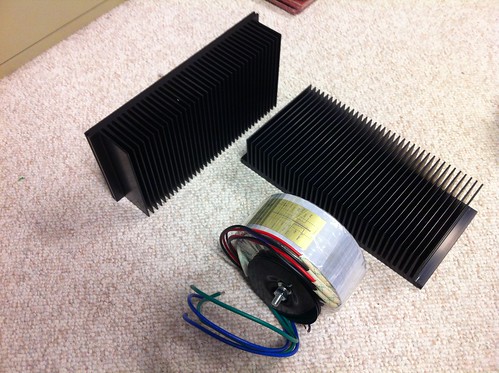
I see you stepped up for the one with the shield. What's the voltage?
😎
The same as the otherwise recommended one... 400VA at 18V. I also picked up a 50VA 15V one for the impending hypnotize B1 build. Separate build thread for that once I get around to it! 🙂
Now that I think about it... What am I supposed to do with the purple shield wire? Attach to star ground?
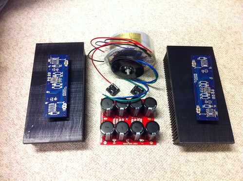
Got some bits from Mouser today. Does anyone else find soldering large electrolytics extremely satisfying?
Any commentary on the initial layout? I'm also considering going sans power switch entirely despite having bought the DPDT relay. i would just switch it on at a dedicated power strip. That would keep the build as simple and clean as possible.
Also, I was considering putting the transformer in a separate "floor" box to minimize any chance of hum. I haven't seen that execution in the F5 before though so thought I would see if there are any concerns there. The only thing that I would want to do is make sure the umbilical between the boxes isn't too long. Maybe 2-3 feet... thoughts?
Last edited:
- Status
- Not open for further replies.
- Home
- Amplifiers
- Pass Labs
- oneplustwo F5 build thread