I did not make one, but I probably could.
What dimensions? Are you mounting outputs on the board?
What are the hole placements?
😎
What dimensions? Are you mounting outputs on the board?
What are the hole placements?
😎
I did not make one, but I probably could.
What dimensions? Are you mounting outputs on the board?
What are the hole placements?
😎
Hello Nelson,
I would want to mount the outputs on the board - well on the edge of the board I guess?
Mono boards and I was hoping to use the IRFP240's that I have assuming they can do the duty.
Dimensions are not critical would design the box around them...
I really dont know how you find the time to be so active in this forum and produce all the kit you do as well!
Much obliged.
WM
I would totally buy a PLH board.
Yes I am sure the list here will grow!
Nelson one other thing I have just thought of - I would want the version with paralleled output devices i.e Fig 11 in your writeup?
Thanks again.
WM
O.K not growing... 🙂
Never mind Nelson clearly not worth it!
I will look at recreating JLHs bipolar endeavours instead.
WM
Never mind Nelson clearly not worth it!
I will look at recreating JLHs bipolar endeavours instead.
WM
I am working on an all-FET version of the JLH class A, where the ouput is very similar to (OK, nearly a copy of..) the PLH amplifier. So it is a 4 transistor design. But I use split supply (plus/minus 24 V).
Hello,
Thanks yes I would be interested - I need the PCB foil pattern though which is why I have switched to the JLH bipolar 1969 version - I have got a foil pattern for that.
Ta
WM
Thanks yes I would be interested - I need the PCB foil pattern though which is why I have switched to the JLH bipolar 1969 version - I have got a foil pattern for that.
Ta
WM
Here is the schematic. I have ordered the PCBs, and as soon I receive them, I can start mounting the components before initial testing.
I plan to use a 2x18 V 500VA transformer common for the two channels. I also have two quite large heatsinks (0.3 K/W) which I plan to use. This amplifier favours high quiescent current, so maybe I can set this as high as 1.8 A...
I plan to use a 2x18 V 500VA transformer common for the two channels. I also have two quite large heatsinks (0.3 K/W) which I plan to use. This amplifier favours high quiescent current, so maybe I can set this as high as 1.8 A...
Attachments
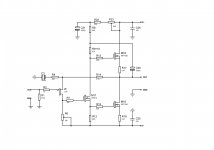
You are perhaps missing the opportunity to adjust the balance between
the positive and negative output drives. Look at the pots on the PLH
schematic.
😎
the positive and negative output drives. Look at the pots on the PLH
schematic.
😎
Yes I know what you mean. I have not quite decided yet if I am going to use a pot as done in the PLH amplifier. For the time being I have thought of using to resistors instead of the pot and then have the possibilty to change between push pull and something like halfway single ended.
Here is the schematic. I have ordered the PCBs, and as soon I receive them, I can start mounting the components before initial testing.
I plan to use a 2x18 V 500VA transformer common for the two channels. I also have two quite large heatsinks (0.3 K/W) which I plan to use. This amplifier favours high quiescent current, so maybe I can set this as high as 1.8 A...
This is certainly looking good to me! - Nelson can help crit the design I am not up to that - but I mean the concept and the components!
I have a pair of Conrad MF35-151.5 heatsinks rated at 0.21C/Watt and I have IRFP240s - so yes very happy with the direction this is going knutn!
Thanks
WM
Last edited:
Knut,
You can balance the drive on the output transistors by splitting the 0.47 ohm sense resistor into a centre tapped pair of 0.235 ohms, with the the feedback resistor R14, the bootstap capacitor C20 and the loudspeaker connected to the same point. I used this approach in the latest version of my interpretation of ZenV4 - similar topology to J Aleph.
See: http://www.diyaudio.com/forums/pass-labs/161716-aleph-current-source-mod.html
- Status
- Not open for further replies.
- Home
- Amplifiers
- Pass Labs
- JLH/PLH PC Boards?