Funny Ha Ha! forgot about that volume dial.
I'm being both theoretical and practical. I can get the SPL I like from both the F5 and the BA-3 after adding the 02 pre to the system. As a purist approach I'd like to drive the amp directly from the DAC and eliminate the pre. Having a PC/flac source, I initially removed the sound drivers but have since found not that much difference between those and external volume control. Hence the interest in bumping up the amp output a bit. It's also an opportunity to better understand the science under the hood.
I have 24.4 - 25.6 secondaries depending on the time of day. The system is SE.
Edit: I've asked Paul for the SF efficiency about a dozen times but he never answers. That's another quest for another adventure.
Last edited:
Ah, so you need extra gain. Funny how wording changes the meaning of the question. I'm a bit surprised that 30 dB in the BA-3 isn't enough. The BA-3 article suggests several ways to increase gain by changing a few resistors. With the F-5 you can increase the feedback resistors to get higher gain.
So your transformer is probably rated at 10A per secondary. Divide by 1.8 gives 5.6A MAX into a capacator input filter. Derate 50% and you're at 2.8A. If you want to go higher, you need a bigger transformer.
I'm a bit surprised that 30 dB in the BA-3 isn't enough. The BA-3 article suggests several ways to increase gain by changing a few resistors. With the F-5 you can increase the feedback resistors to get higher gain.So your transformer is probably rated at 10A per secondary. Divide by 1.8 gives 5.6A MAX into a capacator input filter. Derate 50% and you're at 2.8A. If you want to go higher, you need a bigger transformer.
Ah, so you need extra gain. Funny how wording changes the meaning of the question.
Exactly! That's why I'm trying to discover if I made an error during construction/adjustments and am taking the time to understand all the components one at a time. I'll report back when the new trimmers are in.
Thanks again for all your help and information.

Last edited:
So I did a one step backwards two forward trick. With a new chassis in mind, I needed top adjustment access in the trimmers so I ordered new pieces. The multi-turns allowed getting the correct readings without touching P3 - as posted. The P3s are still single turn but with top side adjusting screws.
Next step - I went back and read the earlier posts but didn't see a clear answer to this question. Should the bias boards (without the output boards) be added and adjusted next, or should the bias boards and output boards be powered as an independent combo with readings/adjustments done independent of the front end? I believe I saw both approaches in the earlier posts.
(Hoping for one of those nice pictorial BA-3 build guides from 6L6 soon)
Next step - I went back and read the earlier posts but didn't see a clear answer to this question. Should the bias boards (without the output boards) be added and adjusted next, or should the bias boards and output boards be powered as an independent combo with readings/adjustments done independent of the front end? I believe I saw both approaches in the earlier posts.
(Hoping for one of those nice pictorial BA-3 build guides from 6L6 soon
)
Last edited:
Treat the Front-end as a unit for testing separate from the bias and output boards.
Treat the bias board and output board as one unit.
So; test your PSU alone,
then the Front-end,
then the bias/output stage,
then tie everyting together and hope for no smoke.
There will be a BA guide, I've been waiting for Mosfet sets for a long time, they are finally enroute.
Treat the bias board and output board as one unit.
So; test your PSU alone,
then the Front-end,
then the bias/output stage,
then tie everyting together and hope for no smoke.
There will be a BA guide, I've been waiting for Mosfet sets for a long time, they are finally enroute.
Great, PSU and front end are done. I finished testing and re-mounting the mosfets on the outboards last evening, so I'll do that combo this afternoon.
Glad to hear about the planned guide. I'm sure it will encourage many new builders. There is lots of info many great tips throughout the thread but it's pretty scattered - even the second time around.
Thanks
Glad to hear about the planned guide. I'm sure it will encourage many new builders. There is lots of info many great tips throughout the thread but it's pretty scattered - even the second time around.
Thanks
Last edited:
I was able to get all the settings/readings correct, everything wired back together and successfully played music through the amp. A victory of sorts!
However, the power supply is over heating again and begins to emit some smoke when the output boards are attached.
Everything checked out fine with direct connection from PSU to the front end only.
No problems with the PSU directly connected to the bias boards only. For initial turn-on I set the bias to 3.0 VDC. Should I have tried to make that adjustment with the output boards attached??
I did not test the PSU > bias boards > front end combination.
Though my home-made PS boards worked well for months and appeared stable over the past few days, I had planned to get the forum store boards for final assembly. These also still have the lower quality 0.47 resistors. They will be replaced with new Panasonic
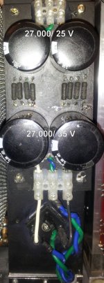
So I might just as well add a fresh set of PSU caps since these have been subjected to some overheating at least twice. When I built this power supply I used what I had which was pairs of 27,000/35 and 27,000/25. I'm assuming matching all of them will perform better.
So I'm asking for some recommendations on what to buy.
Specs:
500/18 Va on each side.
12 output devices each side
Stock build with standard voltage settings as per NP article.
Speakers @ 8 ohm nominal
As mentioned earlier, some mods/experiments to increase output are likely in the future. Should that be a consideration in the new capacitor selection?
However, the power supply is over heating again and begins to emit some smoke when the output boards are attached.
Everything checked out fine with direct connection from PSU to the front end only.
No problems with the PSU directly connected to the bias boards only. For initial turn-on I set the bias to 3.0 VDC. Should I have tried to make that adjustment with the output boards attached??
I did not test the PSU > bias boards > front end combination.
Though my home-made PS boards worked well for months and appeared stable over the past few days, I had planned to get the forum store boards for final assembly. These also still have the lower quality 0.47 resistors. They will be replaced with new Panasonic
So I might just as well add a fresh set of PSU caps since these have been subjected to some overheating at least twice. When I built this power supply I used what I had which was pairs of 27,000/35 and 27,000/25. I'm assuming matching all of them will perform better.
So I'm asking for some recommendations on what to buy.
Specs:
500/18 Va on each side.
12 output devices each side
Stock build with standard voltage settings as per NP article.
Speakers @ 8 ohm nominal
As mentioned earlier, some mods/experiments to increase output are likely in the future. Should that be a consideration in the new capacitor selection?
Attachments
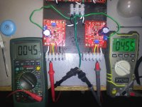
I duplicated this measurement from post #1098
Attachments

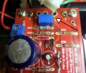
Shaky ground here. Full counter clock wise all the way to the click only reduces it to 3.2 V across the resistor.
Hesitant to try the other way and go higher than what I had. Does the trimmer appear to be in the correct orientation?
@ZM - I apparently misunderstood that earlier conversation/post. Thanks for the clarification - again!!
Hesitant to try the other way and go higher than what I had. Does the trimmer appear to be in the correct orientation?
@ZM - I apparently misunderstood that earlier conversation/post. Thanks for the clarification - again!!
Attachments
Last edited:
- Home
- Amplifiers
- Pass Labs
- Burning Amp BA-3