I am interested in a group buy for Toshiba MOSFETs. We should start a GB thread for this.
I have been asked by PM about sourcing MOSFETs.
You probably all know that Toshiba is stopping all audio devices, MOSFETs and JFETs alike.
The only open source that is known to have sufficient quantities for NNPP match is, as mentioned before, ZhouFang.
It has also been discussed before that his matching is not exactly at F5X operating conditions.
So if you do not wish to purchase from Zhou, the only solution right now is to GB and match yourselves.
We ourselves are in the process of acquiring sufficient devices to support future batches of F5X projects.
But it won't be 6 months or so before we are ready, and then only in the context of supporting the project,
and not as separate devices sets for general sales.
Patrick
F5X varient for small heatsink
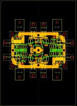
I am working on a variant of Patrick's F5X board that is shrunk to a 2.5" x 3.8" board to be mounted on a 5" x 7" heatsink . Two such heatsinks are attached fin-to-fin to form a heat tunnel, cooled by a very quiet 120 mm fan. Here are images of the layout:
The first image shows the entire heatsink, with the airflow from top-to-bottom (yeah, I know, this is upside-down from normal conventions). The MOSFET placement was carefully chosen for heat distribution. The design is for 100-120 watts dissipation per heatsink.
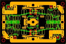
The second image is the PCB. The resemblance to EUVL's layout should be apparent. Due to space restrictions, the 220 ohm feedback resistors are replaced with Caddock MP820's attached to the heatsink.
There are 2 major jumpers (not shown) for the X connections. Without any other jumpers, the board provides an F5X. Two jumpers provide a floating balanced togolopy, (the X's are connected). Two more jumpers activate Nelson's P3 adjustment. And finally, two more jumpers ground everything for initial adjustment or for use as 2 independent unbalanced F5 amplifiers. The jumpers are intended to be made using .1 inch shunts, but soldering is possible.
Balanced input connections are made using a 4 pin header. At the corners are 2 pin headers for connections to the source resistors for initial adjustment.
I am working on a variant of Patrick's F5X board that is shrunk to a 2.5" x 3.8" board to be mounted on a 5" x 7" heatsink . Two such heatsinks are attached fin-to-fin to form a heat tunnel, cooled by a very quiet 120 mm fan. Here are images of the layout:
The first image shows the entire heatsink, with the airflow from top-to-bottom (yeah, I know, this is upside-down from normal conventions). The MOSFET placement was carefully chosen for heat distribution. The design is for 100-120 watts dissipation per heatsink.
The second image is the PCB. The resemblance to EUVL's layout should be apparent. Due to space restrictions, the 220 ohm feedback resistors are replaced with Caddock MP820's attached to the heatsink.
There are 2 major jumpers (not shown) for the X connections. Without any other jumpers, the board provides an F5X. Two jumpers provide a floating balanced togolopy, (the X's are connected). Two more jumpers activate Nelson's P3 adjustment. And finally, two more jumpers ground everything for initial adjustment or for use as 2 independent unbalanced F5 amplifiers. The jumpers are intended to be made using .1 inch shunts, but soldering is possible.
Balanced input connections are made using a 4 pin header. At the corners are 2 pin headers for connections to the source resistors for initial adjustment.
Attachments
There were some discussions about distortion cancellation of the F5X at the build thread.
The original discussion in 2008 (!!!) you can find here.
http://www.diyaudio.com/forums/pass-labs/121228-f5-power-amplifier-24.html#post1538833
Fitzfish and I also stated on a couple of occasions that the measured distortion spectrum does not differ between ground X, floating X, and the H connected (see NP's article on F5 Turbo, the balanced schematics towards the end). However, the floating X or H will allow the circuit to operate with single ended inputs (-Vin connected to Gnd), which is not the case for the grounded X.
Patrick
I shall do a F5X turbo end of this year after the F5X Preamp.
When are you going to release some info on the FX5 Preamp? We are getting very curious.
When the first proto is finished, probably not before end of August.
It comes in 2 cases (one for amp and one for power supply) that match the F5X power amp case.
Circuit similar to the F5X power amp.
With push buttons, remote control, relay source selector and attenuators.
Attenuator uses Caddock MK132 or Vishay S102 resistors.
Enough details for now ?
")
Patrick
It comes in 2 cases (one for amp and one for power supply) that match the F5X power amp case.
Circuit similar to the F5X power amp.
With push buttons, remote control, relay source selector and attenuators.
Attenuator uses Caddock MK132 or Vishay S102 resistors.
Enough details for now ?
Patrick
- Status
- This old topic is closed. If you want to reopen this topic, contact a moderator using the "Report Post" button.
- Home
- Amplifiers
- Pass Labs
- F5X -- the EUVL Approach