Original frame design that looks nice for internal work also. Congratulations.
I hope its fully stable with no traces of oscillation even with the MOSFET pins extension cables.
I have seen such cables before from a few guys, but if you got a generator & scope, do pass a 10kHz square to see its butter smooth with no ringings.
How did you like it, and in what kind of system?
I hope its fully stable with no traces of oscillation even with the MOSFET pins extension cables.
I have seen such cables before from a few guys, but if you got a generator & scope, do pass a 10kHz square to see its butter smooth with no ringings.
How did you like it, and in what kind of system?
Original frame design that looks nice for internal work also. Congratulations.
I hope its fully stable with no traces of oscillation even with the MOSFET pins extension cables.
I have seen such cables before from a few guys, but if you got a generator & scope, do pass a 10kHz square to see its butter smooth with no ringings.
How did you like it, and in what kind of system?
sorry, newbie question, is there any other way to test it without generator and oscillator?
so far I like it a lot (laptop-ibasso d7-dcb1-gainclone-lektor)...
No, not really any other good substitute for confirming that. I.e. if its really perfectly smooth.
If it had any real issue though, it would whistle through the tweeter or it would go weirdly hot for the current setting you chose, or it would buzz, wander voltage etc.
So don't get yourself worried.
If it had any real issue though, it would whistle through the tweeter or it would go weirdly hot for the current setting you chose, or it would buzz, wander voltage etc.
So don't get yourself worried.
Regarding caps.
I have the BOM 35v 4700uf nichicon.
I also have some 35v 4700uf gold tune nichicons but as you know they do not fit exactly( I have the dcb1 mez board).
What is everyone's thoughts regarding sound quality difference and if you go with gold tune how do you best install them?
I have the BOM 35v 4700uf nichicon.
I also have some 35v 4700uf gold tune nichicons but as you know they do not fit exactly( I have the dcb1 mez board).
What is everyone's thoughts regarding sound quality difference and if you go with gold tune how do you best install them?
Darbost, Very nice tidy build. Congratulations, I like the exposed heat sinks idea.
Salas, Still amazed with my stage 1.5 Hotrod DCB1, listened to 3 different source inputs yesterday, PS3 -->Pioneer Elite (yuck, think it was the PS3, not the Elite), Oppo 83 ---> Sony ES --->(Meh, not too bad, sorta closed in), Oppo 83 --->DCB1 = Magic.") Amplification in all cases was the Pass F5. Alison Krauss is in my home!
Amplification in all cases was the Pass F5. Alison Krauss is in my home!
Thank you soooo much.
Ron
Salas, Still amazed with my stage 1.5 Hotrod DCB1, listened to 3 different source inputs yesterday, PS3 -->Pioneer Elite (yuck, think it was the PS3, not the Elite), Oppo 83 ---> Sony ES --->(Meh, not too bad, sorta closed in), Oppo 83 --->DCB1 = Magic.
Amplification in all cases was the Pass F5. Alison Krauss is in my home!Thank you soooo much.
Ron
Last edited:
Regarding caps.
I have the BOM 35v 4700uf nichicon.
I also have some 35v 4700uf gold tune nichicons but as you know they do not fit exactly( I have the dcb1 mez board).
What is everyone's thoughts regarding sound quality difference and if you go with gold tune how do you best install them?
Use what fits dimensionally. There isn't much space for hacking it.
Darbost, Very nice tidy build. Congratulations, I like the exposed heat sinks idea.
Salas, Still amazed with my stage 1.5 Hotrod DCB1, listened to 3 different source inputs yesterday, PS3 -->Pioneer Elite (yuck, think it was the PS3, not the Elite), Oppo 83 ---> Sony ES --->(Meh, not too bad, sorta closed in), Oppo 83 --->DCB1 = Magic.
Thank you soooo much.
Ron
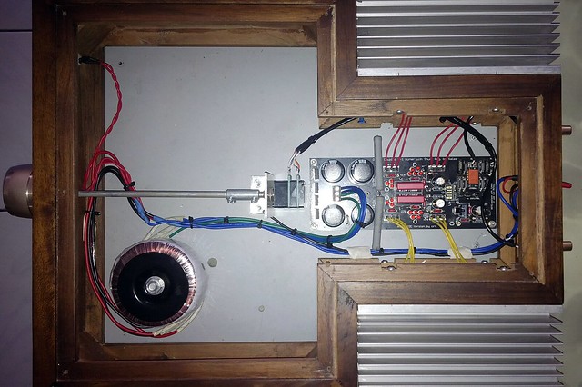
 Enjoy.
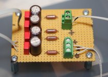
here's the innards
Nice build but, after such a careful layout, why did you position the input pot right next to the transformer ?
Salas: Thanks for the compliment and infos. So far I don't hear anything abnormal comes out from it. I guess I won't worried about generator and scope. Yes, it's a TKD 10K pot. Sharp eyes!
KatieandDad: I placed the pots there because I couldn't fit the pots at the back section just at side of the pcb. (I was restricted with the size that I wanted to achieved.)
But I think I should be able to move the transformer and place metal plate between transformer and the pots. But what's the effect of placing pots near transformer?
All: thank you for the compliment
Salas: Thanks for the compliment and infos. So far I don't hear anything abnormal comes out from it. I guess I won't worried about generator and scope. Yes, it's a TKD 10K pot. Sharp eyes!
KatieandDad: I placed the pots there because I couldn't fit the pots at the back section just at side of the pcb. (I was restricted with the size that I wanted to achieved.)
But I think I should be able to move the transformer and place metal plate between transformer and the pots. But what's the effect of placing pots near transformer?
All: thank you for the compliment
With the transformer in close proximity to the input circuitry you increase the chances of stray mains pick-up. You should aim to keep the transformer as far away from the inputs as possible.
With the transformer in close proximity to the input circuitry you increase the chances of stray mains pick-up. You should aim to keep the transformer as far away from the inputs as possible.
Thanks
Now it looks like this after a drill, a shift and some tidies.
Re: Hot Rod DCB1
I was told that going with 4 X 1watt 18R resistors would be a good increase from the 1/2watt 68R on the BOM.
The problem is the Takman's I ordered, the leads are too thick. I have looked on Mouser, Digikey, and Newark to order some other ones but none are available with the desired specs.
What is your advice?? What resistors should I go with to give my DCB1 a performance boost? Ones that fit and are available would be cool.
Pass DIY Addict
Joined 2000
Paid Member
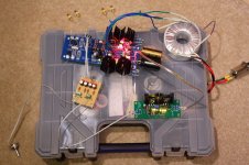
My DCB1 build
I just finished my DCB1 build and wanted to share what I've done so far. So far, I've only made a few measurements and run a square wave through it. Listening comes tonight - I can't wait!
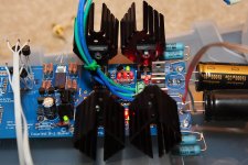
I used a 100VA 15-0-15 Antek transformer (goal is to use bigger sinks and push bias to about 1A or so. The transformer provides about 15.8VAC which rectifies to about 20.4VDC. The rails for the DCB1 run at -9.83 and +10.23v.
With a 20R bias set resistors, I can measure 1.74v drop across +rail resistor and 1.71v drop across -rail. The resulting bias level is about 86mA and I get 0.3mV and 0.7mV offset at the output. The sinks closest to the PS caps show a 10c rise and the next ones show a 6c rise over ambient. The MUR820 diodes show no temp increase.
I changed the Rset resistor to 10R which doubles bias to ~160mA and the sinks now show 16c and 14c temp rise. The diodes are a bit warmer (but no where near the sink temps). Increasing the bias seems to increase the offset to 1.0mV and 1.1mV. The middle two JFETS in the matched quad measure the same at about 8.57mA. The outer pair measures about 8.56mA and 8.59mA (this is from memory - I have the numbers written down at home).
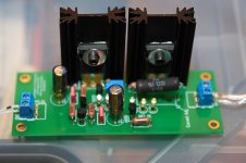
I had the same problem as HiFi Rookie with resistor leads being too thick, so I just laid them down across the pads and soldered them that way. I also left the "key" output resistors mounted higher above the board for easy swapping to some vishay nakeds when they arrive.
I used one of Salas' regulator boards provided by dvb-projekt to power the LDRs. I tapped the +rail cap for input to the regulator (20.4VDC) and adjusted it to a perfect 5.00VDC output. That first sink gets a bit warm at 51c (a 29c rise) - I was thinking of putting a resistor in series with the power supply to the regulator board to bring the supply voltage down a bit to reduce heat on the MOSFET.
Using George's control circuit for the LDRs (100k stereo log pot, 100R current limiters, and a 100uF cap followed by 0.47uF caps), the LDRs get a minimum voltage of 1.62V and a maximum of 2.18V. This allows the resistance of the LDRs to vary from 22R to about 6k7 ohms.
I'm looking forward to giving it a listen tonight!
The last element is building a nice chassis. Funny, I was already envisioning something very much like what Darbost showed above - very nice design work! I am also contemplating the addition of an MV-04 based remote control kit from e-bay for the input switching and volume control. I have to explore some chassis options first...
Thanks in advance to Salas for sharing this great design with us! I also appreciate George sharing his LDR design, Uriah for providing the LDRs, and Spencer for the JFETs!
I just finished my DCB1 build and wanted to share what I've done so far. So far, I've only made a few measurements and run a square wave through it. Listening comes tonight - I can't wait!
I used a 100VA 15-0-15 Antek transformer (goal is to use bigger sinks and push bias to about 1A or so. The transformer provides about 15.8VAC which rectifies to about 20.4VDC. The rails for the DCB1 run at -9.83 and +10.23v.
With a 20R bias set resistors, I can measure 1.74v drop across +rail resistor and 1.71v drop across -rail. The resulting bias level is about 86mA and I get 0.3mV and 0.7mV offset at the output. The sinks closest to the PS caps show a 10c rise and the next ones show a 6c rise over ambient. The MUR820 diodes show no temp increase.
I changed the Rset resistor to 10R which doubles bias to ~160mA and the sinks now show 16c and 14c temp rise. The diodes are a bit warmer (but no where near the sink temps). Increasing the bias seems to increase the offset to 1.0mV and 1.1mV. The middle two JFETS in the matched quad measure the same at about 8.57mA. The outer pair measures about 8.56mA and 8.59mA (this is from memory - I have the numbers written down at home).
I had the same problem as HiFi Rookie with resistor leads being too thick, so I just laid them down across the pads and soldered them that way. I also left the "key" output resistors mounted higher above the board for easy swapping to some vishay nakeds when they arrive.
I used one of Salas' regulator boards provided by dvb-projekt to power the LDRs. I tapped the +rail cap for input to the regulator (20.4VDC) and adjusted it to a perfect 5.00VDC output. That first sink gets a bit warm at 51c (a 29c rise) - I was thinking of putting a resistor in series with the power supply to the regulator board to bring the supply voltage down a bit to reduce heat on the MOSFET.
Using George's control circuit for the LDRs (100k stereo log pot, 100R current limiters, and a 100uF cap followed by 0.47uF caps), the LDRs get a minimum voltage of 1.62V and a maximum of 2.18V. This allows the resistance of the LDRs to vary from 22R to about 6k7 ohms.
I'm looking forward to giving it a listen tonight!
The last element is building a nice chassis. Funny, I was already envisioning something very much like what Darbost showed above - very nice design work! I am also contemplating the addition of an MV-04 based remote control kit from e-bay for the input switching and volume control. I have to explore some chassis options first...
Thanks in advance to Salas for sharing this great design with us! I also appreciate George sharing his LDR design, Uriah for providing the LDRs, and Spencer for the JFETs!
Attachments
Last edited:
From your text I gather that you fully understand what you are doing and what the circuit should be doing.
I would not recommend more than 200mA in a Mez unless you arrange for other sinks and do the "leg trick" though. Its "voiced" up to there max as it is standing.
The newer Hypno was adapted full hot-rod wise, but you could match it for 1A level if you will do as above. Look for the thread "Using the HYPNOTIZE as a general shunt reg PCB" to see the "leg trick". Congrats, nice W.I.P by the way.
Just got my board today. I got the parts ordered. Going with the Antek 50Va 12V transformer. Not going to hot rod it unless necessary. Originally was just going to build a B1 but saw these boards in the forum store when ordering some Honey Badger boards so I decided to go this way. I've been reading this thread for half the day. Looking forward to building it. My Pre's as of now are a Bryson .5B, Dynaco PAS3 and a Sony digital. None of them see past 9:00 on most days so I think I need something with less gain. Looking forward to joining in the fun.
Blessings, Terry
Blessings, Terry
- Home
- Amplifiers
- Pass Labs
- Mezmerize DCB1 Building Thread