Salas, tank you for the guidance.
I finally got my measurements, the jfets are real indeed.
Now I've more questions (of course )
)
Where to put them?
I've got 2 matched pairs:
8.29 + 8.28 | 8.48 + 8.5
like this into position 1, 2, 3, 4?
(according to your orders following this post...
Then I have 6 unmatched:
6.60 | 7.13 | 8.00 | 8.37 | 8.45 | 9.63
are these good enough for a good B1?
Does the order of the unmatched jfets matter?
Thanks!
I finally got my measurements, the jfets are real indeed.
Now I've more questions (of course
)Where to put them?
I've got 2 matched pairs:
8.29 + 8.28 | 8.48 + 8.5
like this into position 1, 2, 3, 4?
(according to your orders following this post...
Then I have 6 unmatched:
6.60 | 7.13 | 8.00 | 8.37 | 8.45 | 9.63
are these good enough for a good B1?
Does the order of the unmatched jfets matter?
Thanks!
It looks OK
[…]
*Before you will note down IDSS let it run for a minute to settle. Stick each Fet on paper and write the mA figure next to it for future reference if you got many pieces.
Where to put them?
I've got 2 matched pairs:
8.29 + 8.28 | 8.48 + 8.5
like this into position 1, 2, 3, 4?
Yes position them like that.
Then I have 6 unmatched:
6.60 | 7.13 | 8.00 | 8.37 | 8.45 | 9.63
are these good enough for a good B1?
Does the order of the unmatched jfets matter?
Thanks!
They are good enough for the rest of positions in the PSU section. They can be randomly put there without odd effects. Since you already measured their IDSS though, you could put the 8.37 & 8.45 units at the positions between C550 and C560 on the board.
put the 8.37 & 8.45 units at the positions between C550 and C560 on the board.
Thank you very much! Will do!
(Maybe a word or two on why to put them there? Would help me sneak upwards on my learning curve
)david
To have more comparable running currents in the five Leds strings. Because those two Fets are their tail constant current sources. Thus keeping their total VF per side closer which keeps +/- rails closer.
The two Fets work under those BJTs Vbe voltage though (~0.6-0.7V VDS) so their IDSS lessens in situ and comes closer than in normal testing so its not a big deal.
But since you asked do it like that. For aesthetic purposes mainly. Don't expect measurable differences in performance by having exact +/-V rails voltages or somewhat off in this design.
To have more comparable running currents in the five Leds strings. Because those two Fets are their tail constant current sources. Thus keeping their total VF per side closer which keeps +/- rails closer.
The two Fets work under those BJTs Vbe voltage though (~0.6-0.7V VDS) so their IDSS lessens in situ and comes closer than in normal testing so its not a big deal.
But since you asked do it like that. For aesthetic purposes mainly. Don't expect measurable differences in performance by having exact +/-V rails voltages or somewhat off in this design.
Thank you! I‘ll sort them anyway. Made me think of building LEGO-gear and aligning the bricks by their logo [emoji846]
(I must confess that I was close to start over because I didn’t match the resistors...)


Almost there
I'm through with the greater part of solder-job. I love it!
Next will be plugging the led's (want to try to match them in circuit, just for fun + learning), and my great challenge: hooking up the toroid.
I've a toroid ts50va, just like the BOM suggested. Now, before I blow up anything, how do I connect it correctly?
Pri: 230V blue-blue: is clear.
0: green-yellow: earth out?
sec: 2 x 15 V red-red / orange-orange: uhm ...
I'll sift through the web for clues,
I'll build my bulb-tester,
and maybe someone will (hopefully ) be faster with a seven-word answer?
thank you!
david
I'm through with the greater part of solder-job. I love it!
Next will be plugging the led's (want to try to match them in circuit, just for fun + learning), and my great challenge: hooking up the toroid.
I've a toroid ts50va, just like the BOM suggested. Now, before I blow up anything, how do I connect it correctly?
Pri: 230V blue-blue: is clear.
0: green-yellow: earth out?
sec: 2 x 15 V red-red / orange-orange: uhm ...
I'll sift through the web for clues,
I'll build my bulb-tester,
and maybe someone will (hopefully
) be faster with a seven-word answer?thank you!
david
We need a link to your transformer's datasheet to answer about wiring by colors. Most probably its red 15, red+orange common, orange 15. Green/yellow probably a screen that goes to mains earth.
Thank you Salas
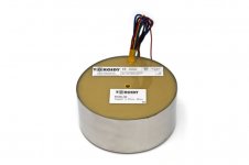
It the toroidy TSAS0050 supreme audio,
Nominal power 50VA
Input voltage 230V
Output voltage 15V
Didn't find much more on it, but I'd say your information ... songs good to me. I trust you know better than me how to connect a tranny
david
Attachments
They should had a datasheet with diagram and wire color coding. Not just a label. Most probably its to be configured as I suspect but you could also email them to confirm. Else you should wire it as likely but measure it unloaded for correct AC voltages and confirm no tendency to overheat because the secondaries phasing must also be done correctly. Dim bulb tester is a must especially when not experienced and without a scope to see the terminals phasing.
They should had a datasheet with diagram and wire color coding.
Thank you, Salas.
Torrid seem to never sleep, here's the PDF they sent just a few moments ago.
(the color code is not corresponding with mine, though)
I'm confident the transformer is working very well, and will do the tests and measuring to get it right.
You are very helpful, thank you very much!
david
Attachments
The datasheet refers to wire colors other than you originally described for the product in hand as you mentioned.
...
I got a datasheet for a different transformer and first did not realize it...
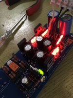
Got the correct one today with still other wire color. Mentally replaced them, took a deep breathe and
HURRA!
Attachments
Last edited:
don't test it without sinks more than briefly.
Thank you very much, Salas
I would not have come so far without your advice.
I won’t run B1 without heatsinks.
Speaking of which, is the mini-sink on the to-220 required? I don‘t seem to be able to mount it because the board is quite dense...
Thank you!
David
Its required.There are some small enough types. Maybe you can simply use a fitting raw piece of aluminum or copper instead. Or chop the sink you got a little.
Or, as it just now dawned on me, if someone has no sinking solution in hand, but needs to test now, couldn't he just mount another nowhere connected TO-220 device back to back or top and up to augment the thermal capacity of the activated one until he finds a more elegant way?
Any TO-220. Even a broken one.
- Home
- Amplifiers
- Pass Labs
- Mezmerize DCB1 Building Thread