Hi John, thanks, we are keeping well for now. Wishing the same for you and your people.
The WDPhono3s has an ECC83 common cathode output stage biased at 110V plus 1K series buffer resistor after the output capacitor. Zo=1/S so for its 1.25mS transconductance the ECC83 can have Zo=800Ω. +1K=1.8K i.e. high output impedance.
The Technics RS-BX626 cassette deck states 400mV/800Ω output i.e. weak Zo again but not as much. Because 20K>10xZo the phono will tolerate a 20k Log pot. For best transients comfort I would personally prefer passing the 20xZo ratio though. But its not a deal breaker. For all your other sources a 20K pot is absolutely no concern.
Thanks for your reply Salas, and glad you’re all keeping well.
I’m wondering if 25k might be a good compromise between the 20k and 50k instead then? But what of the input resistor value? Unfortunately the maths/theory side of this is currently way beyond my abilities. Basically, whatever you suggest to go for in my situation, I’ll buy it
")
25K sounds like a fair deal in your case then. Use 330K input resistor at your DCB1. The idea is because Rin >> Rpot it will not influence its curve.
Rin is a safety path, keeps the JFET's gate firmly referenced to ground for it will not flap in the breeze if a brief mechanical discontinuity occurs in a pot. This DC coupled circuit would give DC at the output if unsettled.
Rin is a safety path, keeps the JFET's gate firmly referenced to ground for it will not flap in the breeze if a brief mechanical discontinuity occurs in a pot. This DC coupled circuit would give DC at the output if unsettled.
I’ll order a 25k Alps Blue then and see how it goes...
Sorry to interfere, but: when I was sourcing the parts for DCB1, I had troubles finding a 20k alps blue, and asked for advice. Received a hint to an alternative and was very pleased. (Obviously, I couldn‘t compare it to an alps)
It’s post #605 of the dcb1 build Thread... (sorry, inserting link doesn‘t work)
Last edited:
Sorry to interfere, but: when I was sourcing the parts for DCB1, I had troubles finding a 20k alps blue, and asked for advice. Received a hint to an alternative and was very pleased. (Obviously, I couldn‘t compare it to an alps)
It’s post #605 of the dcb1 build Thread... (sorry, inserting link doesn‘t work)
Thanks for the suggestion, but went to post 605 of this thread, and there was no mention of a pot? Are you sure it was in this thread? Cheers.
Hello,
I have been working on this Mezmerize project on and off. Now that I have the time to do it, I tried to finish it but stumbled upon this problem.
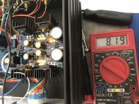
DC offset on the IRFP240 side is 8.19V (yes 8.19 VOLTS!)and rising; on the IRFP9240 side it's (-)16mV. But V+ = 10.61v, V- = 1.99v; on the 68Rs, 2.11v and 1.99v.
I can hear the click a few seconds after turn on and all the LEDs are lighted.
I use an Antek AS-0512 2x12V 50VA Torroidal Trans with the 2 green wires tied together going into the CT and the 2 blue wires into the 2 sides. I tried connecting with one blue and green tied together but it resulted with only the 3 LED group on the IRFP240 lighting up - rest are dead. With the green wires together I get all LEDs lighted up.
Any suggestions how to troubleshoot is greatly appreciated. Thanks!
Eric
I have been working on this Mezmerize project on and off. Now that I have the time to do it, I tried to finish it but stumbled upon this problem.
DC offset on the IRFP240 side is 8.19V (yes 8.19 VOLTS!)and rising; on the IRFP9240 side it's (-)16mV. But V+ = 10.61v, V- = 1.99v; on the 68Rs, 2.11v and 1.99v.
I can hear the click a few seconds after turn on and all the LEDs are lighted.
I use an Antek AS-0512 2x12V 50VA Torroidal Trans with the 2 green wires tied together going into the CT and the 2 blue wires into the 2 sides. I tried connecting with one blue and green tied together but it resulted with only the 3 LED group on the IRFP240 lighting up - rest are dead. With the green wires together I get all LEDs lighted up.
Any suggestions how to troubleshoot is greatly appreciated. Thanks!
Eric
Thanks for the suggestion, but went to post 605 of this thread, and there was no mention of a pot? Are you sure it was in this thread? Cheers.
Hi johnm
Uhm... I think something went out of my control.
The post is here (I hope it's correct this time): https://www.diyaudio.com/forums/pass-labs/181552-b1-preamp-build-thread-61.html#post5937294
The pot here: KKA2531S28 Precision Electronics Corporation | Potentiometers, Variable Resistors | DigiKey
Last edited:
Hi johnm
Uhm... I think something went out of my control.
The post is here (I hope it's correct this time): https://www.diyaudio.com/forums/pass-labs/181552-b1-preamp-build-thread-61.html#post5937294
The pot here: KKA2531S28 Precision Electronics Corporation | Potentiometers, Variable Resistors | DigiKey
Thanks very much! That looks perfect - Much better tolerance than the Alps Blue too. Good catch. Ordered
Thanks very much! That looks perfect - Much better tolerance than the Alps Blue too. Good catch. Ordered
The honor goes to codyt (and Salas and the forum of course!)
Hello,
I have been working on this Mezmerize project on and off. Now that I have the time to do it, I tried to finish it but stumbled upon this problem.
DC offset on the IRFP240 side is 8.19V (yes 8.19 VOLTS!)and rising; on the IRFP9240 side it's (-)16mV. But V+ = 10.61v, V- = 1.99v; on the 68Rs, 2.11v and 1.99v.
I can hear the click a few seconds after turn on and all the LEDs are lighted.
I use an Antek AS-0512 2x12V 50VA Torroidal Trans with the 2 green wires tied together going into the CT and the 2 blue wires into the 2 sides. I tried connecting with one blue and green tied together but it resulted with only the 3 LED group on the IRFP240 lighting up - rest are dead. With the green wires together I get all LEDs lighted up.
Any suggestions how to troubleshoot is greatly appreciated. Thanks!
Eric
Hi
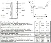
The transformer's datasheet directs that the nearby green & blue secondary wires should go to the CT input point while the remaining green and blue should go to the sides of the input connector.
When in doubt test the AC results without having the transformer connected to the board. Tie the nearby green & blue together and measure looking for 12VAC between each free secondary wire and the tied point.
When 12-0-12 correct VAC result is established for the transformer wiring, without suspicious heating or buzzing, use only that way. Any other possible errors should be due to construction and/or parts problems of the PCB itself.
We can try correct those too, but start with a sure transformer configuration. Then we will debug.
Attachments
Hi
The transformer's datasheet directs that the nearby green & blue secondary wires should go to the CT input point while the remaining green and blue should go to the sides of the input connector.
When in doubt test the AC results without having the transformer connected to the board. Tie the nearby green & blue together and measure looking for 12VAC between each free secondary wire and the tied point.
When 12-0-12 correct VAC result is established for the transformer wiring, without suspicious heating or buzzing, use only that way. Any other possible errors should be due to construction and/or parts problems of the PCB itself.
We can try correct those too, but start with a sure transformer configuration. Then we will debug.
Thanks Salas! Will try again the other pair because the first time I did that the trafo became really hot.
Hi Salas,
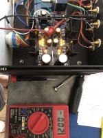
Just got the trafo connected as you indicated. I guess I bundled the wrong pair of blue and green last time. Now there's no overheating in the trafo, all the LEDs still shine brightly so and the readings for DC offset, V+ and V-, voltages on the 68R//68Rs are still the same as previously gathered. Could the error(s) be in the output section? Where do I start first? Thanks for any help.
Here are some photos...
Attachments
The voltage across 68R (pin to pin) indicates the mA running in the current sources. There are two 68R in parallel per side. So CCSmA=Vdrop/34.
The rails voltage output must be checked at the other side of the PSU section between the three free pads.
Are they healthy at about +/-10V DC?
If yes, there could be a broken JFET in the signal pair of the large offset channel. You can't be sure about exact few mVDC offset with the multimeter at 20V scale but surely 8.19 VDC reading indicates a problem.
They are V+ = 10.61 and V- = 10.8. on the parallel 68Rs, V=2.11, 1.99
So the supplies are working as expected now. About 30mA CCS each and correct rails. Minus rail was low before the transformer got rearranged I think?
How do I check for the broken JFET? Are those the 4 2SK70BLs that are in line near the relay? On that high offset, moving the scale to mDCV generates a reading of 1 which I assume is beyond its scale.
Yes those. A quick way is to power off and measure each one for Ohm between drain and source pins without desoldering them. Healthy ones should be 30-50 Ohm. That is for finding a shorted one. If the test is inconclusive the problem might be gate pin related they have to be desoldered and checked as for IDSS.
mV meter scale is good for reading healthy low DC offset channel outputs. When output is few Volt that scale is overloaded.
- Home
- Amplifiers
- Pass Labs
- Mezmerize DCB1 Building Thread