Good Morning !
Hi Gents ,
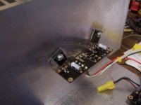
I just received my boards from the guys at chipamp.com ( very nice work )
one problem though , no parts list or Schematic ..... Can someone please point
me in the right direction .... I screwed up one set of China boards already
many thanks, Richard
Hi Gents ,
I just received my boards from the guys at chipamp.com ( very nice work )
one problem though , no parts list or Schematic ..... Can someone please point
me in the right direction .... I screwed up one set of China boards already
many thanks, Richard
Hi Gents ,
I just received my boards from the guys at chipamp.com ( very nice work )
one problem though , no parts list or Schematic ..... Can someone please point
me in the right direction .... I screwed up one set of China boards already
many thanks, Richard
Hi Rich
I think this is the BOM, from the chipamp site.
Steve
Attachments
I have been snowed in for approaching 4days.
I have not tried to dig me nor my car out yet.
We've about an inch of wet snow, city in crisis!
Edinburgh is usually as bad.
I suspect all cities that get intermittent snow are like that.
We drivers refuse to prepare for the conditions.
Snow tyres, and/or snow chains or winter tyres fitted with snow/ice studs are the start for preparing for driving in snowy conditions.
Driver training for the conditions would move some way to avoiding clogged streets.
I recall a female motorist struggling against a kerb on a crossfalled roadway @ ~10mph.
I passed her, with 4 studded wintergrips fitted, far more safely than she was (not) coping. Yet she sounded her car horn at me !
She did not realise the danger she was putting herself and other road users in due to the fact she had not prepared for winter. If one refuses to prepare the vehicle to travel safely in snowy conditions then it should be illegal and insurance banned to take the vehicle out in snowy conditions.
I'm can't see how we could legislate for being caught out by unexpected snow cover while we are already out.
Last edited:
Hi Gents ,
just a quicky .... why do I have Q6-7 on my boards ? they are not mentioned on the parts list ....
This is not going to be a straight forward Aleph 30 . After talking it over with Bill ,it seems I can get another 20 watts pch out of my heat sinks .. Can I use another 4 fets ?
Rich
just a quicky .... why do I have Q6-7 on my boards ? they are not mentioned on the parts list ....
This is not going to be a straight forward Aleph 30 . After talking it over with Bill ,it seems I can get another 20 watts pch out of my heat sinks .. Can I use another 4 fets ?
Rich
Hi Gents ,
just a quicky .... why do I have Q6-7 on my boards ? they are not mentioned on the parts list ....
This is not going to be a straight forward Aleph 30 . After talking it over with Bill ,it seems I can get another 20 watts pch out of my heat sinks .. Can I use another 4 fets ?
Rich
Looking at the spreadsheet, they seem to be used for the mini-a, but the a30 uses separate boards with a bunch of the same transistors. If I'm interpreting correctly, then just a way of managing the heat dissipation.
You pretty much have it right but if you add a fet to each output board without trimming the bias back you are adding 50% more bias current.
Rich, with your higher than normal rail voltage a third fet per board would add some 8 ohm power to the amp, but you will need matched triples. You can attain the same results by increasing the bias in your pairs. The only caveat is intimate fet contact with your heatsinks for maximum heat transfer. They will be approaching 40 watts dissipation per fet.
Rich, with your higher than normal rail voltage a third fet per board would add some 8 ohm power to the amp, but you will need matched triples. You can attain the same results by increasing the bias in your pairs. The only caveat is intimate fet contact with your heatsinks for maximum heat transfer. They will be approaching 40 watts dissipation per fet.
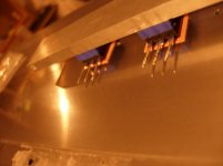
I have been thinking about the placement and contact of the fets ... I have opportunity to
use a bar over the top of the fets trapping them against the sink . I could also connect the pins by wire which would allow me to space the fets more evenly on the sink .
Would I compromise the signal by using wire ?
I have ordered aluminium flat bar , 20mm x 8mm for the back of the fets .
I would also have to re-think the internal layout now I have the output board .
I am thinking about some kind of shielding in the form of PTFE or a metal enclosure
around the AC input at the rear of the amp.
A few things here I could use some feedback on please Guys ,
Thanks, Rich
I the absence of an informed answer I'll chip in....I have been thinking about the placement and contact of the fets ... I have opportunity to
use a bar over the top of the fets trapping them against the sink . I could also connect the pins by wire which would allow me to space the fets more evenly on the sink .
Would I compromise the signal by using wire ?
I have ordered aluminium flat bar , 20mm x 8mm for the back of the fets .
I don't like the idea of a bar at the back of the FETs. Right now you have a FET to heatsink interface that you polished to get good conduction of heat. If you add a bar, then you have a second interface that can resist transfer. Maybe this can be ok, but for what benefit? If the bar was from copper (or diamond!), then I could see how it might work.
For the bar on front, I've seen this in builds. I wonder would it be as effective to simply screw on a heatsink to the front of the FET? Maybe this would reduce the thermal coupling of the FETs. The bar does look good though.
For the wires, I'm curious myself....
A bar could insure improved contact of the fet to the heatsink, just be sure you don't crush the fets. There would not be any appreciable heat extraction from the bars themselves.
You will already need to use wire to run to the output boards if you use them. The only MUST is, if running wires to the individual fets, the gate stopper resistors should be soldered directly to the gate pins.
If the base on your heatsinks are 15mm thick, I would not be too concerned about spreading them out evenly. You can get close to 75mm spacing using the output boards.
Last edited:
Hi,
the clamping bar works even better if the clamp system has some compliance to allow the device to expand and contract with changes in temperature and yet still maintain adequate clamping force.
If each device under a clamping bar could be "pushed" onto the heatsink with the equivalent of a very stiff spring, that introduces the compliance necessary to get the best out of the clamping bar arrangement.
That is why the spring clip type clamps work so well. They are springs "pushing" the device against the heatsink.
This allows better heat transfer than using the hole and bolt method designed into most power packages.
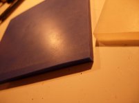
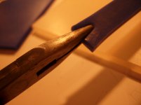
I have some PASS BLUE 60 nm silicone sheet 5mm thick . I have put a piece in some vice grips on the radiator over night at a very similar temp C
The compression would be more even .
BTW, Im only using the bar to avoid putting more holes in the sink
The compression would be more even .
BTW, Im only using the bar to avoid putting more holes in the sink
Attachments
no,I'm only using the bar to avoid putting more holes in the sink
using a clamp bar requires at least one extra hole.
You need a bolt through the clamp on each side of every device and the bolt should be located close to the side of the device.
The clamp bar not be allowed to bend such that a few of the devices are less tightly clamped than their neighbours.
I have some PASS BLUE 60 nm silicone sheet 5mm thick . I have put a piece in some vice grips on the radiator over night at a very similar temp C
The compression would be more even .
Is silicone dimensionally stable at all temps ? I mean, from power on to idle, it will go from ambient to about 60 - 70 - 80 degrees depending how far you push the bias ...
Can you be sure the pressure will be even at those different temps using silicone ?
Just my 2 cents
no offense really, the sheet looks very nice Best regards,
nAr
- Status
- This old topic is closed. If you want to reopen this topic, contact a moderator using the "Report Post" button.
- Home
- Amplifiers
- Pass Labs
- Complete Novice Needs Help