The cap multipliers drop 4v each and depending on current, typically 1.2amps that’s 5w per cap multiplier mosfet or 10w for both rails per channel. Just add this to the typical 50-55w dissipation of the Toshiba’s and mount on a 65w capable heatsink. I have also found that the floor pan of an amp enclosure can handle 10w just fine.
Member liubincalvin might still have a few (from Zhoufang's stock)
That is where the last ones I bought came from. I will check and see.
Russellc
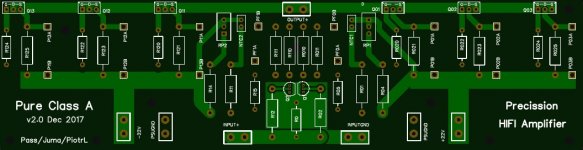
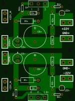
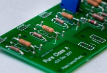
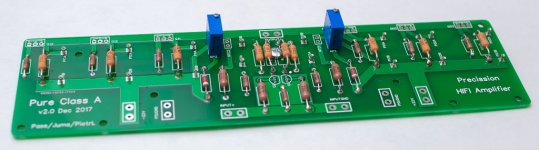
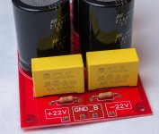
So I have received my PCBs from EasyEDA. I'll have cap multiplier separated from rectifier electrolytes and will keep it separate per channel. May come in handy for future projects. FYI, if somebody is interested, I have attached photo views of PCBs.
Other stuff like toroid, 4U chassis, passives, RCAs, etc. is slowly coming from different parts of the world.
So far one surprise on the way to Yuma's F5 is the cost.... To be honest, I did not sit down and calculate properly all euros needed to be flushed on this. Not that I would park the project if I'd knew, I really want this amp on on my shelf, but the surprise wasn't nice. I agree I could have saved some, but anyway it is still high. This amp has to really sound good now")
So I guess the learning is to carefully plan the supply chain and consider options.
Anyway, the project is going and is exciting
Other stuff like toroid, 4U chassis, passives, RCAs, etc. is slowly coming from different parts of the world.
So far one surprise on the way to Yuma's F5 is the cost.... To be honest, I did not sit down and calculate properly all euros needed to be flushed on this. Not that I would park the project if I'd knew, I really want this amp on on my shelf, but the surprise wasn't nice. I agree I could have saved some, but anyway it is still high. This amp has to really sound good now
So I guess the learning is to carefully plan the supply chain and consider options.
Anyway, the project is going and is exciting
Attachments
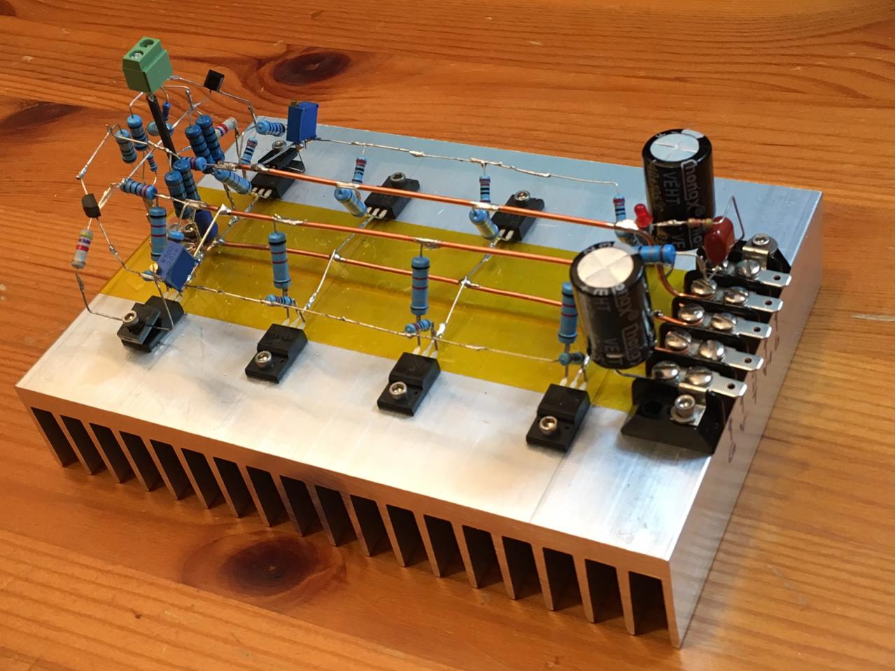
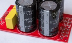
do you have any pictures from a different angle, that is a thing of beauty!I think if one has a PSU and heatsink already, this amp is not too bad. The 2SK2013 and 2SJ313’s can cost a pretty penny. Pcbs are now so cheap or doesn’t save anything to P2P except maybe time.
do you have any pictures from a different angle, that is a thing of beauty!
Sure, from Post 644.
You might like my ACA too:
Last edited:
Thing of beauty indeed
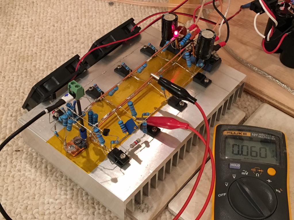
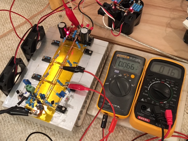
So there is my first issue which I need your help to resolve. Input JFETs have arrived and I thought I'll test them as per the following post http://www.diyaudio.com/forums/soli...asy-mosfet-vgs-measurement-3.html#post5201484
I am using a 20V laptop charger as PS. I set the drain current to about 5mA. I was hoping to see Vgs/Vds to be about 4V but it actually is below 0.3V for N transistor and below 0.5V for the P one.
At the same time the GS and GD P/N junctions seems to be OK, at above 0.7V each when forward biases and blocking when biased in reversed direction.
Will appreciate any comments on that.
I got 10 of each. Out of curiosity really, just wanted to check the difference between them. As per the classic Nelson paper http://www.firstwatt.com/pdf/art_matching.pdf there should be a difference in the set and Vgs should be about 4V.
for a small signal jFET the Vgs = zero volts if you want the Current to be Idss and Vds=10Volts and Tj=25degrees C
As you increase the Nchannel Vgs to slightly negative the Id reduces to less than Idss.
This is shown on the graph in the datasheet.
When the Vgs has increased to -1V the Id is down below 1uA
Read Borbely, he is my expert when it comes to FETs.
As you increase the Nchannel Vgs to slightly negative the Id reduces to less than Idss.
This is shown on the graph in the datasheet.
When the Vgs has increased to -1V the Id is down below 1uA
Read Borbely, he is my expert when it comes to FETs.
Thanks Andrew, this is great stuff.
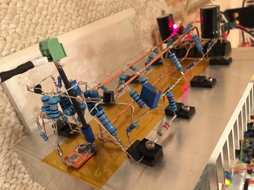
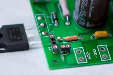
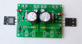
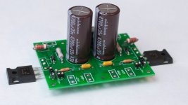
MOSFET are still on their way to Ireland, but I could put together PSU, both cap multipliers and one channel of the amp.
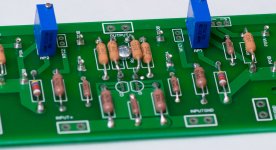
As mentioned previously, I have added socket pins in parallel with source resistors, feedback resistors and also for cap multiplier LEDs and their resistors. This will come handy for experimenting with different setups.
Potentiometers are already set to 0. I have also chosen to use 4.7k resistors in parallel with pots, as it was mentioned earlier in the thread.
MOSFET are still on their way to Ireland, but I could put together PSU, both cap multipliers and one channel of the amp.
As mentioned previously, I have added socket pins in parallel with source resistors, feedback resistors and also for cap multiplier LEDs and their resistors. This will come handy for experimenting with different setups.
Potentiometers are already set to 0. I have also chosen to use 4.7k resistors in parallel with pots, as it was mentioned earlier in the thread.
Attachments
XRK, what are the resistors you are using for the freewire build?
Which resistor are you referring to?
Seems JFETs are harder to find then MOSFETs. I have got 170/74 pieces from few sources and the closest I can get in terms of Idss is 7.00mA for 2sk170 and 5.85mA for 2sj74. The latter result in itself means that it is not probably a BL grade part, if genuine at all in a first place ... BL grade parts are sold out on the diyaudiostore, can you recommend a source of matched JFET pairs by chance?
Hi Piotl,
Some good sources given diyaudio store is current out of stock:
FET Audio | Hi-End Audio Projects
Toshiba 2SJ74 + 2SK170 MATCHED QUAD to 0.03mA AND 4mV 7.2mA-7.4mA Idss Range | eBay
http://www.diyaudio.com/forums/members/nicmac.html
Cheers,
Dennis
Some good sources given diyaudio store is current out of stock:
FET Audio | Hi-End Audio Projects
Toshiba 2SJ74 + 2SK170 MATCHED QUAD to 0.03mA AND 4mV 7.2mA-7.4mA Idss Range | eBay
http://www.diyaudio.com/forums/members/nicmac.html
Cheers,
Dennis
- Status
- This old topic is closed. If you want to reopen this topic, contact a moderator using the "Report Post" button.
- Home
- Amplifiers
- Pass Labs
- F5 with 2SK2013/2SJ313