Thanks guys. I thought I was being so careful when I installed them. I was wearing a ground strap and touched a grounded case right before starting. I handled them only with tongs and not my fingers. I never touched the legs, only the casing and only with the tongs. Maybe sliding it into the holes on the board did it. I use an ESD safe Weller soldering station. Those suckers must be really sensitive. This is the 1st time I've ever had a part ruined by static.
Listened to a bunch more records when I got home. Can't get over how clean & natural my records sound now. I thought they sounded great before, but WOW, it sounds like I'm at the concert. Just so real & natural. Crisp & biting like a live show. I just saw Ed Sheeran a few weeks ago. Sitting back with my eyes closed and listening to his album sounded like I was back at the concert.
Listened to a bunch more records when I got home. Can't get over how clean & natural my records sound now. I thought they sounded great before, but WOW, it sounds like I'm at the concert. Just so real & natural. Crisp & biting like a live show. I just saw Ed Sheeran a few weeks ago. Sitting back with my eyes closed and listening to his album sounded like I was back at the concert.
They just seem sensitive. We have good grounded work stations and even anti static floor wax. The larger die stuff is just fine we don't lose many of the TO-92 but one is to much in the field. For DIY it builds character and trouble shooting skills.
surely you have some left over LU1014?
Pass DIY Addict
Joined 2000
Paid Member
For DIY it builds character and trouble shooting skills.
Reflecting back on my own experiences, it's funny how this was an under-rated skill with my first projects. I stressed over parts and blowing stuff up. While I blow stuff up a little less often now, my trouble shooting skills have improved quite a bit.
Pass DIY Addict
Joined 2000
Paid Member
Just completed lifting the ground leg of R14 and adding a cap in series. I added a 100uF 63v electrolytic cap bypassed with a Wima 0.01uF 63v film cap. This reduced DC offset from a wandering 10-20mV to a rock steady 0.1mV. I then added a jumper across C8 - mostly because it was easier than removing C13. Still listening for differences - it seems to be a rather subtle change.
Next, I want to replace C12||C16 with some Teflon caps. I'll pull C13 at this time. Certainly fun to experiment!
Next, I want to replace C12||C16 with some Teflon caps. I'll pull C13 at this time. Certainly fun to experiment!
Greetings and thanks to the many folks before me in this thread, Pearl Two, and the other lengthy Building a Pass Pearl Two build thread. Of course Nelson, Wayne, and 6L6 get a big thank you. Also many thanks to propitious, bern, nar, and so many others who were either providing answers or asking the questions that have helped me so much on this project. I have read every single post in both Pearl Two and Building A Pearl 2.
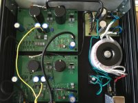
The picture shows the build I have been working on as of this post. So far I have not applied power to the boards. I did check my power supply voltage, both sides are 31.6 volts. This alone was a milestone for me including making my own simple circuit board, a real pleasure.
I have read many comments about taking measurements. Some measurement I have read of in the threads are for the power regulators and the there is the measure from test pads and the bias adjustment using P1. My question/need is a big one but my guess is there is bound to be someone just as ignorant as me that this will help too, so here goes.
What should be measured and how? To illustrate my ignorance; I understand I will need to adjust P1 so that I read 0V DC at the test point as indicated. I assume the meter is set to DC, the Pearl Two is powered on, and that I put the black lead from the meter on ground and the red lead on the test point. However assumptions by those that have my level (or lack of) knowledge can lead to problems. End result I don’t have the confidence to turn this thing on. I really don’t have a clue what else And how to go about doing the necessary checks.
Any help will be much appreciated.
Attachments
Pass DIY Addict
Joined 2000
Paid Member
Double check ALL transistors (part numbers, orientation) and take a flat blade micro screwdriver and physically scratch the PCB between the solder pads on all of the transistors to make sure there are no tiny solder bridges. If you have a variac, bring the voltage up slowly, pause before you get to full voltage, check voltages on power supply resistors (R3/R4) and (R33/R31). This voltage should rise along with the variac. Once you get up to about plus/minus 10v on your power supply, you should be getting some sound out the unit...
Kevin thanks for your reply, I’ll look into the light bulb tester.
Eric thanks for your reply too. I have trip checked parts orientation, I think I have that right. Though I did a visual to check for solder bridges I’ll be pulling the boards to do a physical scratch. I like that idea. While reading your reply I remembered that I once had a variance I used with a guitar amp. It may still be hanging around.
Eric thanks for your reply too. I have trip checked parts orientation, I think I have that right. Though I did a visual to check for solder bridges I’ll be pulling the boards to do a physical scratch. I like that idea. While reading your reply I remembered that I once had a variance I used with a guitar amp. It may still be hanging around.
This questions remains for me. When adjusting P1 where do I place the black and red probes? The problem for me is, having not done this before and not finding a guide on how to, the phrase ‘check voltages on power supply resistors (r3/r4) and(r33/r31) means nothing to me as I simply don’t know where to put the meter probes.
Last edited:
Pass DIY Addict
Joined 2000
Paid Member
My apologies, here is a more detailed account.
Resistors R3 and R4 represent the positive power supply rail. They are arranged in parallel with one another, thus they share the current delivery for the positive voltage. Because of the power supply regulator (U1) the positive power supply voltage will never be more than 24v. To measure the voltage being provided by the power supply, clip your red lead to either leg of either R3 or R4. These are only 10 ohm resistors, so it really doesn't matter which leg of R3 or R4 you measure. They both connect to the positive power supply.
Then connect your black probe to the yellow wire on your PCB - this is the zero voltage ground plane.
Start with your variac turned all of the way down to zero volts. Plug the Pearl into the variac and slowly bring the variac up until you see about 10v or so on the positive power supply for the PCB. This *should* be enough power for the transistors to begin to conduct and for the board to function at some level (though, it will be less than optimal). When you see ~10v on the positive power supply, you should also find -10v on the negative power supply. To measure the negative power supply voltage, move your red probe to either leg of R31 or R33 (the output from the negative voltage regulator) while keeping your black probe connected to your yellow wire. This will confirm that your power supply is functioning properly. The positive and negative power supply rails should move at the same time and be very closely "balanced" as you turn up the variac. When the positive supply reads +5 volts, the negative supply should read -5 volts. As you turn up the variac, you should see both supplies move in unison.
With the power supply at about plus/minus 10 volts, check the output offset. Put one probe of your voltmeter into the center barrel of the RCA jack and the other probe onto the outer collar. This measures the output voltage (with no input signal). This voltage is called "offset". It should be close to zero. IF not, adjust P1 until it gets close to zero.
This will get you started. If transistors are installed with proper orientation and in the right places, there are no solder bridges, the power supply is working properly, and you have offset close to zero, you should be able to connect your turn table and an amp with a cheap/disposable speaker and hear something that resembles music. It may not be pretty while being in an under-voltage state, but it should work.
Thank you so much Eric. Those are very clear instructions and just what I needed to move forward.
If this information was provided elsewhere in the two Pearl Two build threads, I missed it, if so my apologies.
I’ll be looking for that variac today and will be building a light build tester this afternoon.
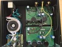
If anyone should note an error in the picture please do share that observation.
If this information was provided elsewhere in the two Pearl Two build threads, I missed it, if so my apologies.
I’ll be looking for that variac today and will be building a light build tester this afternoon.
If anyone should note an error in the picture please do share that observation.
Pass DIY Addict
Joined 2000
Paid Member
Excellent! Thanks for the poke for more details. I stated off with zero understanding of electronics and have learned quite a bit by asking questions here (for almost two decades, now) and by playing around on my own. There are clearly people who know WAY more than I do, and many of them have helped me out along the way. I am very appreciative of those that have helped me learn and am happy to help pass it along!
Eric you are part of the reason this forum works. Someday when I can answer a question for someone, I’ll smile and remember your help. I can’t find my variac, it’s probably gone by now, but I am putting together the bulb tester. Then I’ll suck it up and turn the pearl on. Many thanks.
Hi Kevin, Yes the Pearl Two is making music, beautiful music! I should have posted that! I did build the light bulb tester as you suggested, which when plugged into the Pearl Two told me I was at least ok in that regard.
I gotta say I was surprised at how lovely the Pearl Two sounds compared to the phono stage I had in place before the Pearl Two. There is one small step left, to add heat sinks to the power regulators. Due to the size of the mundorf caps the heatsinks I purchased need to be reduced somewhat. Having ground the heatsinks down this weekend I’ll install them someday this week. I listened to four album sides, so I ran the Pearl Two about an hour, while listening I took temp readings with an instant read digital thermometer. One of the power regulators topped out at 107 degrees F (I think that was the + side) the other regulator topped out at about 99 degrees. When touching them they didn’t feel even that warm. The operating temperature range for the regulators, as stated on the manufacturer’s data sheet, indicates operating temps up to 257 degrees F so I’m guessing I’m pretty safe to go ahead and use the Pearl Two without heat sinks until I get them installed. Thanks for your help.
I gotta say I was surprised at how lovely the Pearl Two sounds compared to the phono stage I had in place before the Pearl Two. There is one small step left, to add heat sinks to the power regulators. Due to the size of the mundorf caps the heatsinks I purchased need to be reduced somewhat. Having ground the heatsinks down this weekend I’ll install them someday this week. I listened to four album sides, so I ran the Pearl Two about an hour, while listening I took temp readings with an instant read digital thermometer. One of the power regulators topped out at 107 degrees F (I think that was the + side) the other regulator topped out at about 99 degrees. When touching them they didn’t feel even that warm. The operating temperature range for the regulators, as stated on the manufacturer’s data sheet, indicates operating temps up to 257 degrees F so I’m guessing I’m pretty safe to go ahead and use the Pearl Two without heat sinks until I get them installed. Thanks for your help.
It seems I spoke to soon. I added the heat sinks to the power regulators. Desoldering was difficult but I managed to get all four power regs out without damaging the boards, or components, or so it seemed. Heat sinks are installed but I now have a dead channel. LEDs light up on both channels but the right channel is dead. I’ll check the continuity on the input and output, beyond that I’m unsure where to look. Any suggestions will be appreciated.
Hi there 6L6 glad to have your thoughts.
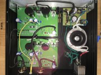
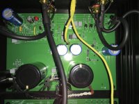
So the picture of the single board is the board that has gone silent. Well there is a sight hiss? coming from the speaker that isn’t making music. The LED on both boards light up the same and fade out at the same time when the unit is turned off. I’ve checked solder joints, scratched for solder bridges (inspected with a magnifying glass afterwards) then reinstalled the board in the chassis (as seen in the pictures), I checked continuity of the input one output wires, cause you never know, they are fine. I then plugged it back up to the stereo and hope against hope still no sound in the right channel. That’s where I am. Also I found the schematic with the voltages which it appears that I should have credited 6L6. Thanks for that! If there are pictures from other angles or of the underside needed I can take those too. Many thanks.
So the picture of the single board is the board that has gone silent. Well there is a sight hiss? coming from the speaker that isn’t making music. The LED on both boards light up the same and fade out at the same time when the unit is turned off. I’ve checked solder joints, scratched for solder bridges (inspected with a magnifying glass afterwards) then reinstalled the board in the chassis (as seen in the pictures), I checked continuity of the input one output wires, cause you never know, they are fine. I then plugged it back up to the stereo and hope against hope still no sound in the right channel. That’s where I am. Also I found the schematic with the voltages which it appears that I should have credited 6L6. Thanks for that! If there are pictures from other angles or of the underside needed I can take those too. Many thanks.
Attachments
- Home
- Amplifiers
- Pass Labs
- Pearl Two