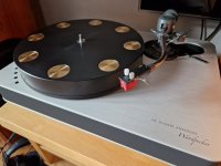
Thanks, here goes:Congrats on your unique build. Would love to see a couple pics of your turntable.
jeff
Attachments
Hello 6L6, I also sent in English, this happened due to the activated automatic translation. I can't see this. Am I classified as a criminal here now? Thanks@dezibaby
Hallo und Grüße!
Dies ist ein englischsprachiges Forum, können Sie bitte auf Englisch posten? Die Verwendung webbasierter Übersetzungen wie Google Translate ist zulässig. Vielen Dank.
~~~
Hello and greetings!
This is a english-language forum, can you please post in english? The use of web-based translation such as Google Translate is acceptable. Thank you.
@dezibaby
The automatic quotation is no problem at all.")
Verify U1 pin 3 is +24V
Verify U2 pin 3 is -24V
What are values -
Q1 vE
Q2 vK
Q2 vE
Voltage across R21
Does P1 operate normally? Can you set 1.5V across R6? Do you have 0v at R16/R17 node?
Is the error on one PCB or both?
Please post a series of well-lit, in-focus photos.
The automatic quotation is no problem at all.
Verify U1 pin 3 is +24V
Verify U2 pin 3 is -24V
What are values -
Q1 vE
Q2 vK
Q2 vE
Voltage across R21
Does P1 operate normally? Can you set 1.5V across R6? Do you have 0v at R16/R17 node?
Is the error on one PCB or both?
Please post a series of well-lit, in-focus photos.
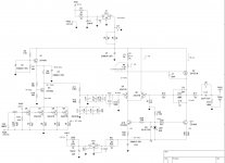
Hello 6L6, checked: U1 P3 +24V, U2 P3 -23.6V, where Pad1 is +33.2V, Pad7 is -34.1V. If I separate the power supply from Pearl then +35.7V/-35.5V. If I set 1.5V across R6, then there are 8.2V on node R16/R17. The circuit boards are from Pass. Actually, apart from the Q3 regime, everything is more or less correct. The voltages on R21-R24 where 20 ohms resistor is installed are 0.12V, in the channel where 10 ohms are left are 0.6V, too much. The only thing I can imagine is that I broke both Q3s when I built them in. Then the reduction of R10 would not have reacted that way, would it? Regards.@dezibaby
The automatic quotation is no problem at all.
Verify U1 pin 3 is +24V
Verify U2 pin 3 is -24V
What are values -
Q1 vE
Q2 vK
Q2 vE
Voltage across R21
Does P1 operate normally? Can you set 1.5V across R6? Do you have 0v at R16/R17 node?
Is the error on one PCB or both?
Please post a series of well-lit, in-focus photos.
If I set 1.5V across R6, then there are 8.2V on node R16/R17.
Replace Q2
ZVP3310 is very sensitive to static electricity during construction, this is a common problem.
Tanks!Ersetzen Sie Q2
ZVP3310 ist während der Bauphase sehr empfindlich gegenüber statischer Elektrizität, dies ist ein häufiges Problem.
Oops! I can't find a ZVP3310. But you certainly know an alternative to the replacement? Thanks.Replace Q2
ZVP3310 is very sensitive to static electricity during construction, this is a common problem.
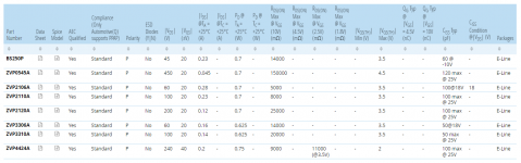
My enthusiasm knows no bounds! Thanks again!Here's the table from Diodes Inc's website
_
Microchip's TP2104N3-G is a P-Channel MOFET with protection diode in T0-92 package. I ordered some to compare in my Pearl II. If a part is out of stock, going to: https://www.findchips.com/search/zvp3310 may help.Oops! I can't find a ZVP3310. But you certainly know an alternative to the replacement? Thanks.
ThanksDer TP2104N3-G von Microchip ist ein P-Kanal-MOFET mit Schutzdiode im T0-92-Gehäuse. Ich habe einige zum Vergleich in meiner Pearl II bestellt. Wenn ein Teil nicht vorrätig ist, kann es hilfreich sein , zu: https://www.findchips.com/search/zvp3310 zu gehen.
Hello 6L6, the ZVP3310 are here, installed, no changes. Actually working regime with grounded signal is not so bad: for Q3 Ue-7.0V; Ub-7.7V; Uk-7.8V means that Q3 is already open. If I set Zero to 0.0V I have 1.7V on R6. Conversely, if U set 1.5V on R6, I have 8.1V on Zero. One can be content with 1.7V on R6, right? Uled=1.7V. What bothers me is that the Q6-Q9 are biased to 0.12V with a 20 ohm resistor. Way too much. If I put the R21-R24 back in 10 ohms, then Q3 is closed again: Ub>Uk. My questions: -can I make R10 even smaller? -does what if I increase R9? Thanks very much!Replace Q2
ZVP3310 is very sensitive to static electricity during construction, this is a common problem.
Looks like your Q6-Q9 devices have an Idss of about 10 ma which is higher than the original design, but it appears you have made the necessary adjustments around Q3, Vec of about 1 volt.The voltages on R21-R24 where 20 ohms resistor is installed are 0.12V, in the channel where 10 ohms are left are 0.6V, too much.
Adjust P1 to get minimum voltage at the output at R17. You are well within the tolerances of the devices. You just needed a higher gate to source voltage on Q2 to match the current coming from Q11. when the current from Q2 equals the current from Q11 the voltage is zero.
Thanks very much! I will get back to you.Looks like your Q6-Q9 devices have an Idss of about 10 ma which is higher than the original design, but it appears you have made the necessary adjustments around Q3, Vec of about 1 volt.
Adjust P1 to get minimum voltage at the output at R17. You are well within the tolerances of the devices. You just needed a higher gate to source voltage on Q2 to match the current coming from Q11. when the current from Q2 equals the current from Q11 the voltage is zero.
Hi all. I reduced R9 to 450 ohms and now at Q3 I have Uk>Ub. Actually it's okay. Only voltage drop to R6=1.7V at Uzero=0V. But I see that I also have Uled in equal value. Because of this! I'm now looking for suitable Led's that bring 1.5V drop. Regards.Looks like your Q6-Q9 devices have an Idss of about 10 ma which is higher than the original design, but it appears you have made the necessary adjustments around Q3, Vec of about 1 volt.
Adjust P1 to get minimum voltage at the output at R17. You are well within the tolerances of the devices. You just needed a higher gate to source voltage on Q2 to match the current coming from Q11. when the current from Q2 equals the current from Q11 the voltage is zero.
Hello everyone, adjusting the LED diode was nothing, because I read in time from Dad that a voltage drop of 1.7V is the reference voltage. Since I applied the Resistor's to adjust. After a long back and forth I have the values at Q3: Ue=9.1V; Ub=9.8V; Uk=9.9V. This worked with R10=8.7kOhm and R9=407 Ohm. Uzero stays around +-30mV, but before +-15mV. It might ring for success if Ur6 didn't equal 1.8V and bias on R21-R24 equaled 70mV. Is that bad? Thanks.Replace Q2
ZVP3310 is very sensitive to static electricity during construction, this is a common problem.
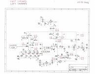
I built the version largely using the recommended components and leaving out C7 which had been determined provided no benefit. Early on I had a couple of ZTX450 failures, otherwise it has gone perfectly. My diagnostic skills are not world beating and the voltages that someone posted quite some time ago (see attached) were very helpful.
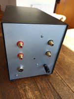
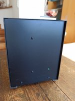
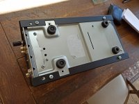
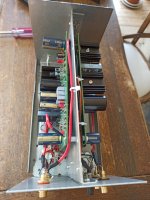
I recently rebuilt the chassis using a recycled component. I would think the approach would be easy to duplicate. The central panel that holds the PCBs stabilises the ends and the black top slides over it all and is held by screws in the bottom. A sheet metal specialist should be able to make it easily -- the bottom and ends could be folded from one piece
I recently rebuilt the chassis using a recycled component. I would think the approach would be easy to duplicate. The central panel that holds the PCBs stabilises the ends and the black top slides over it all and is held by screws in the bottom. A sheet metal specialist should be able to make it easily -- the bottom and ends could be folded from one piece
Attachments
- Home
- Amplifiers
- Pass Labs
- Pearl Two