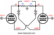
Well, it's a floating bridge amp. Even the follower versions would have problems without actually having some Gnd refrence for the inputs and your "first version" has none. I think any of the unmatched components will then cause an unbalanced condition to average. The average is not the center so less canceling wil take place. You probably could do soemthing similar to what the follower types do and that would be to put resistors from the Drains to Gnd. Maybe 50-100 ohms.
But, in the second version what are you actually driving the amp with? There is no Gnd at all. 2 transformer outputs? How do you actually have 2 floating balanced outputs from a source. I think you need those 2 resistors in that version too
But, in the second version what are you actually driving the amp with? There is no Gnd at all. 2 transformer outputs? How do you actually have 2 floating balanced outputs from a source. I think you need those 2 resistors in that version too
The drawings are only conceptual.
I had the resistors to ground in my "real" version of the first circuit. There's no voltage gain.
I think a transformer might be one way to go, if you're looking for a single-stage with voltage and current gain.
Has anyone tried it?
Thanks
Mike
I had the resistors to ground in my "real" version of the first circuit. There's no voltage gain.
I think a transformer might be one way to go, if you're looking for a single-stage with voltage and current gain.
Has anyone tried it?
Thanks
Mike
The drawings are only conceptual.
I had the resistors to ground in my "real" version of the first circuit. There's no voltage gain.
I think a transformer might be one way to go, if you're looking for a single-stage with voltage and current gain.
Has anyone tried it?
Thanks
Mike
Hi Mike i have patented a similar circuit in the 2005.
It is a single stage push-pull circlotron power amplifier.
Overall, this circuit can be employed also with one single unbalanced input (RCA).
Most balanced amplifier circuit need also a balanced input pair, so its left to other the big problem to realize a unbalanced/balanced circuit. But much sound quality depend on a way in which this circuit is realized, so circuit that need only balanced input are simply "incomplete circuit", in my mind.

Further information you can find in my site:
AMPLIMOS one stage amplifiers, amplificatori audio monostadio
Francesco.
Inverted Circlotron
Mark
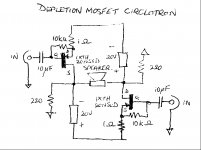
Was thinking about the same thing last week of getting the output stage to provide both gain and power. I came across John Broskie's "Inverted Circlotron" which if you substitute
n-channel mosfets for the tubes shown you have your proposed circuit. I was thinking of doing this with IXYS new IXTH20N50D depletion mosfet which will get around the problem of ground referencing the input with your bias scheme. Attached is the tube CONCEPTUAL version.
Regards
Ejam
Mark
Was thinking about the same thing last week of getting the output stage to provide both gain and power. I came across John Broskie's "Inverted Circlotron" which if you substitute
n-channel mosfets for the tubes shown you have your proposed circuit. I was thinking of doing this with IXYS new IXTH20N50D depletion mosfet which will get around the problem of ground referencing the input with your bias scheme. Attached is the tube CONCEPTUAL version.
Regards
Ejam
Attachments
Using the said IXYS device:
Two simple Current Amplifiers for low impedance loads
Circlotron from the same page:
http://i700.photobucket.com/albums/ww7/paulhynes/CIRC1.jpg
Two simple Current Amplifiers for low impedance loads
Circlotron from the same page:
http://i700.photobucket.com/albums/ww7/paulhynes/CIRC1.jpg
Paul's CIR1 Amp
Ra7
Paul Hynes's amp is configured as a follower with the output taken from the sources. Thus the amplifier has only current gain but no voltage gain. Paul gets away with this by using very low impedance speakers (0.75 ohm) that require lots of current and little voltage gain. Voltage gain is provided by a preceding high gain preamp. His amp while very simple and elegant is specifically designed for a very limited application i.e. his speakers, whereas Mark's is better suited to a variety of speakers.
Regards
Ejam
Francesco
Did a search for your patent and no luck? Care to post the patent or patent pending number.
Regards
Ejam
The patent was presented in date 28 april 2005 ( publication number ITCZ20050009; publication date 28 july 2005)
Finally the patent was released in date 20 july 2009 with this number: "0001363976"
Its name is "Circuito amplificatore monostadio bilanciato" (description is in italian, sorry).
search link:http://www.uibm.gov.it
or: esp@cenet — results view
Francesco.
Last edited:
Mos57
Well the first web address is in Italian and after 2 hours of guessing at various searchs, I could not find it and the second address merely gives the patent number and the inventor. If it is not too much trouble, could you provide a direct link to the patent.
Ejam
Hi Ejam, since the original text was in italian language, i cannnot help much (also summary of invention).
However because i have spent more time and money to patent, i cannot publish here integrally (there are intellectual proprierty, you understand).
Also if the circuit is patent, is easy for someone to try to plagiarize and i not would spend money for legal stuff. At this regards, in this forum there are people more expert than me: is my pleasure to receive advice about.
But if there anybody to have businnes interest , then i can send the document "as confidentially", after agreement subscription.
Now here i can do a brief description of circuit:
- employment of same polarity devices
- employment of a signal transformer
- voltage and gurrent gain
- unbalanced or balanced input signal
- push-pull operation
- single-ended operation
Francesco.
Francesco's Wild Goose Chase
Francesco
Forget it. You obviously want to make things difficult. I thought the public had a right to access patents and that patents protect your intellectual property. The glaring question remains "is the so called invention just an input transformer converting a single ended signal to a balanced signal followed by a mosfet circlotron circuit with the output taken from the drains". If it is, then it's hardly an original invention.
Ejam
I think it can be accomplished with either a single transformer with two independent secondaries, or two matched transformers. Using an output transformer is another possibility. My intention was mostly to illustrate the error in my thinking, but it also highlights just how simple and elegant the JFET input solution really is.
Ejam: I have something on the workbench just for you. (not single stage tho)
Circlotrons are fun to obsess over, like prime numbers.
Cheers,
Mike
Ejam: I have something on the workbench just for you. (not single stage tho)
Circlotrons are fun to obsess over, like prime numbers.
Cheers,
Mike
Ejam,
the circuit in question are at least a transformer followed by a gain stage circlotron, but remain the question that nobody have realized/patented a circolotron stage with voltage gain before.
When one guy try to patent something, he must show that anybody have patented or only published similar object prior him.
As an example, from my present patent i was forced to remove any extension circuits, because similar applications was published on a japanese web site (remember: only published but not patented).
Not so bad at last: i can show its here without problem for my patent
These circuits are very similar with "the amazing circlotron" by Mike.
Francesco.
Attachments
Last edited:
See That Wasn't Too Hard
Francesco
If you look back at John Broskie's Tubecad musings he came up with an "inverted circlotron" circuit back in June 1999 where the output was taken from the drains giving both voltage and current gain. Anyway, thanks for the pdf, will get busy with my Italian.
Mike
Sounds good, when can we get a look at the details?
Ejam
One of the very interesting claims in this patent relates to the fact that the output is ground referenced and from a dc standpoint there is no (dc) voltage present at the load. This is a big difference from the floating tube circlotrons I've worked on (and designed) in the past. (My last design had ground referenced outputs, but it was not the case that the outputs were exactly at ground potential - they could float some volts above or below but were common mode in theory at least.)
The topology also seems to allow for very convenient differential drive ground referenced from a balanced source or even a center tapped IT transformer.
Wonder how well it works. Built a working prototype? Pretty cool idea.
The topology also seems to allow for very convenient differential drive ground referenced from a balanced source or even a center tapped IT transformer.
Wonder how well it works. Built a working prototype? Pretty cool idea.
Sounds good, when can we get a look at the details?
I'd better say 2-3 weeks, just to be on the safe side.
- Status
- This old topic is closed. If you want to reopen this topic, contact a moderator using the "Report Post" button.
- Home
- Amplifiers
- Pass Labs
- Circlotron Meditations