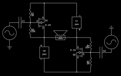
In the below figure, we have exchange the winding arrangement between the two + polariry of batteries and the two RC resistors.
Now the circuit appear a hybrid solution between original SON design and Circlotron design.
I have indicates also the two current I1 and I2 and, as previous, for this circuit we must put I1=I2.
This circuit continue to run in same mode as the first circuit.
Francesco.
Now the circuit appear a hybrid solution between original SON design and Circlotron design.
I have indicates also the two current I1 and I2 and, as previous, for this circuit we must put I1=I2.
This circuit continue to run in same mode as the first circuit.
Francesco.
Attachments
Last edited:
In the previous design we noted that for DC analysis if I1=I2 as we agree, RL is as no there here.
For AC analysis indeed, the RL is in series in beetween the drain and the + B polarity (across the RC).
Now the big difference is that we can think to remove the two RC and the Drains can maintain AC swing.
So doing, we have arrived at circlotron solution.
Francesco.
For AC analysis indeed, the RL is in series in beetween the drain and the + B polarity (across the RC).
Now the big difference is that we can think to remove the two RC and the Drains can maintain AC swing.
So doing, we have arrived at circlotron solution.
Francesco.
Attachments
Interesting perspective, Francesco!
Here's a fun puzzlement for an upcoming meditation:
Looking at the first figure from Meditation #1, if you inject a 1 kHz sine wave into the right half of the circuit, and a 2 kHz signal into the left half, which side of the load would you expect the 2 kHz signal to appear on? (measured from output node to ground)
Interesting perspective, Francesco!
Here's a fun puzzlement for an upcoming meditation:
Looking at the first figure from Meditation #1, if you inject a 1 kHz sine wave into the right half of the circuit, and a 2 kHz signal into the left half, which side of the load would you expect the 2 kHz signal to appear on? (measured from output node to ground)
First of all, thanks much for your encouragement.
If i have right understand you question about fig.1 (starting Son of Zen diagram), if you put 2khz in the right input, then you would obtain the 2khz on the right drain side node of output.
This Son circuit and btw the circlotron, are in my mind, just a two single-ended amplifier, wired in bridge mode (beautiful discover
 ), but also if it'sn't true in deep, this approach help me to understand better its.
Francesco.
(ps): i not have nothing circuit on bench to test. So......
I'm talking about the picture I attached to post #45.
If it helps, feel free to imagine a 100 ohm resistor from output to ground on either side of the load, as is typical. But, it makes absolutely no difference for this puzzle.
And ground resistors or not, there's no net voltage gain. Really. I promise.
If it helps, feel free to imagine a 100 ohm resistor from output to ground on either side of the load, as is typical. But, it makes absolutely no difference for this puzzle.
And ground resistors or not, there's no net voltage gain. Really. I promise.
Last edited:
No, scratch that.
Looking at the attached diagram, a 2Khz signal attached to the right hand input, appears on the left side of the load, which seemed interesting.
Adding the resistors from output to ground changes that, so leave them out for this thought experiment.
Here's how Gerhad Wolf explained it to me:
"This is definitively a buffer, having gain below 1:
The left side of the load follows the right input, reduced by Vgs2 and V3 noise, the right side follows the left input, reduced by Vgs1 and V5 noise.
So you will also hear the power supply ripple."
Mike, already yesterday i could imagine what you should tell me about your strange apparently result: signal on input 1 result on output 2 side and viceversa signal on input 2 result on output 1 side.
But this happens only in follower configuration.
To confirm this you can view that the 2 two outputs are in phase with the relative inputs.
Now this happens in all follower circuit, and is not a strange effect due to circlotron circuit, i think.
To help you to understand which happens, you can remove completely one side of circlotron for a moment.
Remember you that being this circuit a follower you must imagine the GND placed on the Drain side.
Then, the output signal go out from relative source and this is the reason that at the end you view the output signal that in a strange way seems appear from other side of circlotron.
If i am not enough clear, i will post some drawing in the next.
Best regards, Francesco.
Last edited:
The one I built today was the common source version. The performance was lousy. I measured it it before it smoked, which was the builder's fault not the amp's. I just don't think the common source version is workable as a single stage without some special attention. The source follower version (must be the one I built a few years ago) holds more promise as a workable circuit and, initially at least, measures decently.
I wasn't even going to re-visit these single-stagers, but curiosity got the better of me and I have better test equipment these days.
I wasn't even going to re-visit these single-stagers, but curiosity got the better of me and I have better test equipment these days.
Hi Mike, with patience you should examine the following attached files.
In the below figures 1 and 2 are your questions.
You view the input signal 1Khz applied on gate of M1 that (apparently) go out from drain of M2 (side B on R5)
Than you view the input signal 2 khz applied on M2 gate that (apparently i tell you) go out from the drain of M1 (side A on R5).
follow.......
Francesco.
Attachments
Last edited:
In the following is there my personally interpetration of this strange apparently phenomenon.
For that, i have splitted the full circlotron in two halves, considering one half at a time.
Because this entire circui is a classic follower as we have seen from the upper analysis, then i have splitted just in a two separate single ended follower to easily understand it.
the attached figures are related at the upper side.
Being a follower i can imagine a gnd connected to the drain side of M1. The output signal (for all followers) go out from source. So this last signal go in clockwise mode in the output resistor R5, developping the output voltage on side B of R5.
As well as you can note, side B of R5 also should be connected with the Drain of M2 in the case of a complete circuit connected together.
I will Repeat: this is my modest explanation about your intriguing question.
Francesco.
Attachments
Below, there are the figures related to the bottom side of circlotron, as first.
Following analog discourse, we can see the 2 khz input signal applied to gate of M2.
The output go out from source in clockwise mode and cross the output resistor from A to B, so the voltage can envelope on side A of the output resistor R5 that is equivalent to the Drain of M1, if it was connected.
Following analog discourse, we can see the 2 khz input signal applied to gate of M2.
The output go out from source in clockwise mode and cross the output resistor from A to B, so the voltage can envelope on side A of the output resistor R5 that is equivalent to the Drain of M1, if it was connected.
Attachments
Last edited:
At the last i have reassembled the entire circuit, but this time i have wired the bottom input (gate of M2) to ground, for to see what happens.
The remaining input signal on the top side (v2), is also the only output signal (V4)that we can see, following the above expressed arguments.
Therefore, we can see this output signal on side B (that's M2 Drain) as Mike question.
Hope i am not in wrong or annoying nobody, but this question request one detailed answer
Your suggestions are welcome
Francesco
Attachments
Last edited:
Name question
Althought John Broskie is ironic about other many name for the same circlotron circuit (looking at the article posted by Ejam), and at the end also i am agree with him, however i will share any consideration with you:
1. The name “circlotron” was derived from physic machine cyclotron and/or synchrotron to accelerate particles as electrons or protons in a ring circuit.
2. the name “circlotron” is not more easy to pronounce (at least in my language) and have a bad sound for my ears, so i think this name not help for more diffusion in audio equipment, in spite of many advantage over other configurations.
3. The circlotron circuit was employed in the past (almost) always in follower configuration
4. If any people connect the circlotron in casual manner to a driven circuit, then this people obtain a follower operation at 99,99%.
5. There is one only accurate arrangement to obtain full voltage amplification for circlotron.
6. Because of different funtioning as follower or as grounded circlotron looking at posts from 43 to 47 it is not easy to understand about which topology we are referred
From the above arguments, i think it’s more easy to do a specific name for circlotron with gain.
My proposal names for this last are two:
1. “Annular” (or Anular), because it remember a “ring” circuit as the first Circlotron, but it’s more catchy and sound more “sweet”
2. “Circuit 8” or “ Eight”, because the envelope form of the current path.
In this case we can refer to circlotron buffer simply as circlotron, and to circlotron with voltage gain as annular or eight.
My purpose is not to do a new name for an old circuit: It’s only a prompt mode to intend about we are speaking.
Let me know your observation and or your suggested names if you are agree.
Francesco.
Last edited:
- Status
- This old topic is closed. If you want to reopen this topic, contact a moderator using the "Report Post" button.
- Home
- Amplifiers
- Pass Labs
- Circlotron Meditations