you are not testing this correctly.R9 is replaced with 3k3. The output is 25.20v without a load. With a 1k2 resistor load, it drops to 22.17v. Is this OK?
Without a load the CCS is passing ~0.65V/33r =~20mA
The shunt is passing all of this current to ground and holding 25V at the output.
With a 1k2 load the output has dropped to 22V the CCS is still passing ~20mA
almost all of this is passing through the 1k2 load. Almost nothing is passing through the shunt. The shunt cannot regulate properly.

There you go, it almost works properly. A few ohms lower will make it work even better with the load on.
It is not working ideally, the current going through the shunt is IMHO not enough, but you can't really get it too high, because of the shunt transistor is too weak. If in the future you want to improve this, you can replace it with a BD140, and use a 6R8 resistor instead of the parallel 47R. But I'm not sure it's worth pursuing this, your call.
It is not working ideally, the current going through the shunt is IMHO not enough, but you can't really get it too high, because of the shunt transistor is too weak. If in the future you want to improve this, you can replace it with a BD140, and use a 6R8 resistor instead of the parallel 47R. But I'm not sure it's worth pursuing this, your call.
make sure you really know which of the leads are B, C & E.
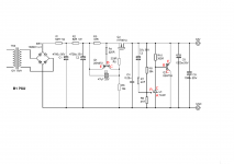
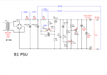
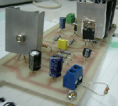
I have attached the PSU scheme indicating CBE and RAC pins. Are these correct?
Attachments
There you go, it almost works properly. A few ohms lower will make it work even better with the load on.
It is not working ideally, the current going through the shunt is IMHO not enough, but you can't really get it too high, because of the shunt transistor is too weak. If in the future you want to improve this, you can replace it with a BD140, and use a 6R8 resistor instead of the parallel 47R. But I'm not sure it's worth pursuing this, your call.
Wow! finally. Thanks, guys for the help. I really appreciate it.
BD140 in place of the 2SA872 and the 2SB716? I will replace the parallel 47R with 6R8 once I get hold of one. Why do you think that this shunt is not worth pursuing?
I'm talking about 2SB716. As an exercise you should get its data sheet and look at it.
http://www.datasheetcatalog.com/datasheets_pdf/2/S/B/7/2SB716.shtml
It is rate for a max 750mW power dissipation, and a max 50mA of current. But we care more about the 750mW. So you set your output voltage to be 25V right? Without a load, the 2SB716 will have to pass all the current, but it can maximally pass only 0.75/25 = 30mA (power = voltage * current). If you happen to want to have a load that draws 28mA, all that is left going through the shunt bjt, the 2sb716, is 2mA. Of course you can set the current through the shunt bjt to be higher, up to 30mA. But if your load all of a sudden stop drawing current, the shunt will get all that additional 28mA, on top of whatever it already passed, and it will fry.
Basically, the 2sb716 is not suited well for your situation. Replace it with a BD140 if you really want to stay with this regulator. A 6R8 resistor will give you about 85mA going through the BD140 which will have to dissipate about 2W, not a problem if you use a small heat sink. A 10R will give you about 55mA through the BD140. This to give you an idea. Start experimenting. Think of the current that goes through the shunt bjt as "reserve" current, that will be used in case there are variations in output voltage and current. Total current that goes through R3 is approximately current through load + current through shunt bjt.
I_R3 = V_R3 / R3.
I_load = V_out / R_load
I_shunt = I_R3 - I_load (approximately)
Have fun.
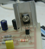
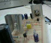
I have changed the parallel 47R with a 6R8 and also changed the TL431 to BD140. The output now with and without load is 25.49v. I am happy with the output results. Thanks.
Voltage across the 6R8 is 0.645v and referenced to Gnd is 32.98v. R2 referenced to Gnd is 33.55v.
The BD140 runs very hot! Very much hotter than the IRF9610.
Voltage across the 6R8 is 0.645v and referenced to Gnd is 32.98v. R2 referenced to Gnd is 33.55v.
The BD140 runs very hot! Very much hotter than the IRF9610.
Attachments
I have changed the parallel 47R with a 6R8 and also changed the TL431 to BD140. The output now with and without load is 25.49v. I am happy with the output results. Thanks.
Voltage across the 6R8 is 0.645v and referenced to Gnd is 32.98v. R2 referenced to Gnd is 33.55v.
The BD140 runs very hot! Very much hotter than the IRF9610.
Wait!!! I said you can replace the 2SB716 with BD140!!! Leave the TL431 in place.
I hope that's what you did.
Edit: BTW, now the measurements look about right. About 95mA on tap. What's not used by the load goes through the BD140. You should use a heat sink on bd140 such that it's not very hot to touch.
Last edited:
a shunt regulator works by feeding a near constant current into the system.
Then the shunt passes more and more current to the return lead until the voltage falls to the set point.
If you change to the 6r8 the CCS passes 95mA.
If you have zero current through the load, then all of that 95mA will pass through the shunt.
You must design the CCS and the Shunt and the heatsinks to survive all the different operating conditions you are likely to impose on it.
This willy nilly method of swapping components around has already damaged components. Keep going like this and your refuse sack will soon be full.
This willy nilly method of swapping components around has already damaged components. Keep going like this and your refuse sack will soon be full.
To his defense, I was the one who recommended the 6R8 and BD140 change.
- Status
- This old topic is closed. If you want to reopen this topic, contact a moderator using the "Report Post" button.
- Home
- Amplifiers
- Pass Labs
- Help with B1 PSU