Just for testing replace the tl431 with a zener so you know for sure you got the right voltage reference. Once it works you can just put your tl431 back in.
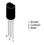
I have replaced the R1 and R2 and the Caps. But the TL431 has three legs. How do I fix the zener and which direction?
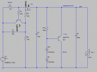
I have replaced R1 and R2 with 5.6R 1w resistors. Both the caps are changed to 220uF. While waiting, I hook up the transformer:
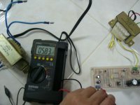
a) the output is 05.83v (img 'output after change R1 and R2')?
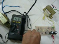
b) R2 referenced to Gnd = 35.76v
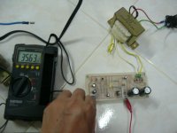
c) R3 refernced to Gnd = 35.63v
d) voltage accross R3 = 6.53v
Did I burned something?
a) the output is 05.83v (img 'output after change R1 and R2')?
b) R2 referenced to Gnd = 35.76v
c) R3 refernced to Gnd = 35.63v
d) voltage accross R3 = 6.53v
Did I burned something?
Attachments
The zener voltage you should choose to be around the output voltage that you want. To test with the zener, take out R8 and R9.
It looks like too much current is being drawn now. Is it still the 470R load?
Sorry I did not inform you. There's no load.
probably.b) R2 referenced to Gnd = 35.76v
c) R3 refernced to Gnd = 35.63v
d) voltage accross R3 = 6.53v
Did I burned something?
What is the voltage across R1?
What is the voltage across R2?
Is the voltage across R3 = 6.53V?
Was it ~600mV before your changes?
Then Q2 is blown.
Sorry I did not inform you. There's no load.
Please use a load for testing. What is the exact voltage that you want at the output? Then I can give you better advice.
probably.
What is the voltage across R1?
What is the voltage across R2?
Is the voltage across R3 = 6.53V?
Was it ~600mV before your changes?
Then Q2 is blown.
a) voltage across R1 =~0.210
b) Voltage across R2 =~0.013
c) voltage across R3 = 6.50v
d) it was 0.646v before the changes
I will change Q2
make sure you really know which of the leads are B, C & E.a) voltage across R1 =~0.210:- I=V/r=.21/5.6=37.5mA
b) Voltage across R2 =~0.013:- I=.013/5.6=2.3mA
37.5mA - 2.3mA = 35.3mA not passing R2, where did the current go?
c) voltage across R3 = 6.50v =damaged
d) it was 0.646v before the changes
I will change Q2
Please use a load for testing. What is the exact voltage that you want at the output? Then I can give you better advice.
24v and the schematic you gave is the correct output.
I have changed Q2 and added in a 470R 1w resistor. It goes from the output and connect to the 0. The output is 3.6v.
voltage across R1 = ~0.213
voltage across R2 = ~0.013v
across R3 = 0.651
Last edited:
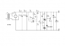
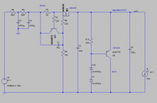
OK the, the 2sb716 will not work with my previous schematic because it can't deal with so much current. Here I adapted the schematic to your situation. This one you can use for testing.
For this, use a 1k2 1/2W resistor as load.
For this, use a 1k2 1/2W resistor as load.
Attachments
Last edited:
If you really wanted a regulator that shines with B1, have a look at the salas v1 regulator that he uses in the direct coupled B1. You'll only need the positive side of it, and change the zener to give you higher voltage. That regulator will outperform this one in every respect.
I'm not saying you should not fix this one, you should, and then build the other one, and compare them. You will not be sorry.
I'm not saying you should not fix this one, you should, and then build the other one, and compare them. You will not be sorry.
If you really wanted a regulator that shines with B1, have a look at the salas v1 regulator that he uses in the direct coupled B1. You'll only need the positive side of it, and change the zener to give you higher voltage. That regulator will outperform this one in every respect.
I'm not saying you should not fix this one, you should, and then build the other one, and compare them. You will not be sorry.
I have put my name for a couple of his boards at the Group Buy. Should I use the salas v1 regulator and forget about this one?
I changed the Q2, now the output with the 470R 1w is 9.20v and without load is 18.70v.
voltage across R3 = 0.651v
OK the, the 2sb716 will not work with my previous schematic because it can't deal with so much current. Here I adapted the schematic to your situation. This one you can use for testing.
For this, use a 1k2 1/2W resistor as load.
I do not have the caps and zeners with me. Need to source tomorrow. I'll like to thank you and Andrew very much for helping. I appreciate it. Maybe I'll just use Salas's scheme.
Last edited:
I have put my name for a couple of his boards at the Group Buy. Should I use the salas v1 regulator and forget about this one?
salas v1 is a much better regulator, IMHO.
I changed the Q2, now the output with the 470R 1w is 9.20v and without load is 18.70v.
voltage across R3 = 0.651v
I can only think that you reference isn't setup right.
salas v1 is a much better regulator, IMHO.
I can only think that you reference isn't setup right.
Better spend time on a better regulator then. There's risks in Salas's B1 as I note in his thread. It is late over here in KL.
Better spend time on a better regulator then. There's risks in Salas's B1 as I note in his thread. It is late over here in KL.
The risk is with DCB1. If you want just a regular B1, then all you need is the positive salas v1 shunt reg.
BTW, I found what your problem is in your current regulator. Replace R9 with a 3k3 resistor and you will get around 25V out without a load. If the voltage stays the same with a load of 1k2 or 1k4, then it works fine.
The TL431 in your original circuit is setup for an output of about 18.3V.
You are a great man. Thanks. I'll get those resistors tomorrow morn. I was searching through the 'Building a symmetrical psu B1 buffer' thread. I should have look at this earlier but 2sk170 is hard to find.
Should I wired both the 24v wires together?
No, that would probably short the transformer!!
what was going through my head when I posted was that it looked like a centre tapped transformer, rather that a transformer with two separate 24V windings... If that is the case then the voltage between either of the two outside wires and the centre wire should be around 12V AC (assuming good transformer regulation)... If you factor in poor transformer regulation this could be a quite a bit higher, and the recitified voltage would be probably around the 18V mark which seemed to be what you were getting.
If indeed the transformer is a CT unit, then there should be 24V between the two outside wires, and it should measure around 12V for either side to the centre wire. whilst the printing on the top shows 24V on either side and zero volts in the middle, I'd be checking it to see if it is really the case
")
I probably should have read all the posts (or not posted at all under the influence of alcohol) , as I now see you did have readings higher than 18V and I've probably only succeeded in confusing the issue.
Tony.
Replace R9 with a 3k3 resistor and you will get around 25V out without a load. If the voltage stays the same with a load of 1k2 or 1k4, then it works fine.
R9 is replaced with 3k3. The output is 25.20v without a load. With a 1k2 resistor load, it drops to 22.17v. Is this OK?
- Status
- This old topic is closed. If you want to reopen this topic, contact a moderator using the "Report Post" button.
- Home
- Amplifiers
- Pass Labs
- Help with B1 PSU