

I guess we'll find out when we see him next year
and then all will realize that my and AR2's love is based on fact -- that I'm gorgeous Blonde , 60-90-60 , 2m tall Domina , you can't ask Dame for age ....
and then all your amps will be mine

Attachments

shouldn't it be 90-60-90 ?
naah .. ' here or there , what's that between friends
60-90-60 Domina
Eer, haven't we met before ?
(ps : you left with the shackle keys. Don't worry, the MD said i'll be fine in a couple of years)
BA2 cascode front end
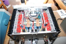
I have compleated my BA2 amp and thought I would post some comments on the sound of the amp. The amp was built into a old Perreaux chassis. At some time I may build two mono amps as I have another transformer (ANATEK AN-4438). At this time the bias is set to 100ma, after installing the top cover the heat sinks got hotter than I liked, also the amp will be installed into a cabinet. How does it sound? Very good, in comparision with my PASS INT150 the sound is very close as it should be, as it is cut from similar cloth. The INT is a more detailed but you have to do listen to a lot of differen't types of music to tell the difference. The BA2 is a little congested in the lower mid range compared to the INT, perhaps that is the second harmonic from the P channel Fets. Compared to the original Perreaux it is hands down a better amp, the Perreaux had good bass but was thin in the midrange where the music lives. The last time I built a power amp was around 1972 so this has been a return to the roots of DIY and a learing experience as most of my career was in digital design. In Summary any time you can build a power amp that will compete with kbuck designs it is worth doing, no I will not give up my INT150 but I could live with the BA2 without regret.
I have compleated my BA2 amp and thought I would post some comments on the sound of the amp. The amp was built into a old Perreaux chassis. At some time I may build two mono amps as I have another transformer (ANATEK AN-4438). At this time the bias is set to 100ma, after installing the top cover the heat sinks got hotter than I liked, also the amp will be installed into a cabinet. How does it sound? Very good, in comparision with my PASS INT150 the sound is very close as it should be, as it is cut from similar cloth. The INT is a more detailed but you have to do listen to a lot of differen't types of music to tell the difference. The BA2 is a little congested in the lower mid range compared to the INT, perhaps that is the second harmonic from the P channel Fets. Compared to the original Perreaux it is hands down a better amp, the Perreaux had good bass but was thin in the midrange where the music lives. The last time I built a power amp was around 1972 so this has been a return to the roots of DIY and a learing experience as most of my career was in digital design. In Summary any time you can build a power amp that will compete with kbuck designs it is worth doing, no I will not give up my INT150 but I could live with the BA2 without regret.
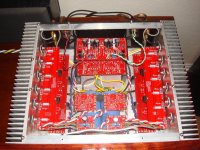
I finished mine up late last night and did some pre flight checks. Set the bias to 150mv across the source resistors for testing. Got the DC offset set to couple millivolts on both the output and the front end. Tonight will be some final adjustments and see how warm it gets( got to remember to bring home the IR temp gun from work). Then I'll hook it to old set of Advent speakers to make sure it works properly. If all goes well then I'm move it inside to my man cave and listen away. I think I'll turn the bias up some as after 1/2 hour last night the sinks were not very warm. How do I determine the bias amperage I can't remember the formula to calculate it. I built it using the DiyAudio boards and used .47 ohm source resistors as Nelson recommend a lower resistance value when not using the 6 pairs of outputs. I will try post some pics tonight also. I built it a with an external power supply so I can use the supply for several different Pass designs.
Chad
Chad
BA2 cascode front end
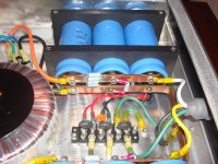
Backbones: The power supply consist of a ANATEK AN-4438 transformer that's rated at 38.8 v @5.8 amps and 37.5 v@12.8 amps, at one time I was going to use two of the above Xformers one for each channel but ran out of room in the chassis. The capacitor bank one for each channel along with a seperate diode bridge consists of two 9,000uf 75volt caps for the postive and the same for the negative side with 10uf film caps for each pos/neg side. The power supplie gives me 53 volts +/- at current bias levels. Perhaps you misunderstood me, this is a very good amp and yes it can stand a little more break in as it has around 20 hours of power up time. My experience on break in is after a reasonable time it is your ears that start changing rather than the electronics. Pior to the PASS INT150 I was running Jeff Rowland model 1's used as mono blocks, the BA2 is the equal of them and in upper mids surpassed the JR's. The speaker's I currently have are a pair of Thiel CS2.2, and two design's that I have built. Zaph design TMM waveguide and Zaph ZA 5.5. My favorite is the TMM waveguide. Most of my listening is with 70% TV home theater and 30% music all of which is 2 channel only. I do have a 15 inch sub. I will try to remember how to post pictures and will get back .
Backbones: The power supply consist of a ANATEK AN-4438 transformer that's rated at 38.8 v @5.8 amps and 37.5 v@12.8 amps, at one time I was going to use two of the above Xformers one for each channel but ran out of room in the chassis. The capacitor bank one for each channel along with a seperate diode bridge consists of two 9,000uf 75volt caps for the postive and the same for the negative side with 10uf film caps for each pos/neg side. The power supplie gives me 53 volts +/- at current bias levels. Perhaps you misunderstood me, this is a very good amp and yes it can stand a little more break in as it has around 20 hours of power up time. My experience on break in is after a reasonable time it is your ears that start changing rather than the electronics. Pior to the PASS INT150 I was running Jeff Rowland model 1's used as mono blocks, the BA2 is the equal of them and in upper mids surpassed the JR's. The speaker's I currently have are a pair of Thiel CS2.2, and two design's that I have built. Zaph design TMM waveguide and Zaph ZA 5.5. My favorite is the TMM waveguide. Most of my listening is with 70% TV home theater and 30% music all of which is 2 channel only. I do have a 15 inch sub. I will try to remember how to post pictures and will get back .
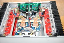
Well its up and running. I biased it to about 200mv on the source resistors. I'll run it like this for awhile but I can go more if I want, I can keep my hands on the sinks for about 45-50 seconds before it gets a little to warm for me. The sound is very nice. Plus it has no turn on or off thump like my Adcom GFA5500. Its holding about 1-2 mv on the output. The front end is still drifting a little bit but its under 18mv. I have few finishing touches left to do, like getting few more Allen head bolts for power supply rails, etc.(I forgot how to count when I ordered them I guess.)
Nelson thank you for sharing your great amps. It sounds wonderful.
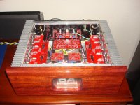
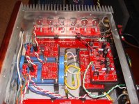
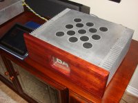
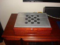
As you can see in the attached pictures I built the amp and power supply in separate enclosures. This is so I can use it with this amp and the BA-1 also. The BA-1 boards are the blank boards in this enclosure. I have set up so I can move the speaker outputs and the inputs, flick a switch on the back and listen to single ended BA-1 once I populate the boards. I also have an F5 planned as my boards arrived from the DIY store. This will go in another chassis yet to be built and use this power supply.
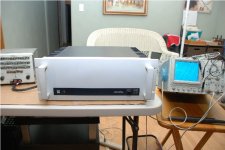
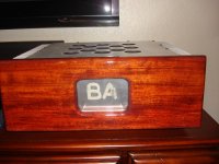
I need some help with designing a Burning Amp logo to be engraved in the front plexiglass panel. It will be edge lit with red led's so it is burning when the amp is on. Problem is I suck at graphic design. The usable area is 4 inches wide by 2 3/4 inches tall. The one that is current installed was done free hand with a router as a proof of concept. I want take a nice design to an engraver I have used and get a good looking one made.
Chad
Nelson thank you for sharing your great amps. It sounds wonderful.
As you can see in the attached pictures I built the amp and power supply in separate enclosures. This is so I can use it with this amp and the BA-1 also. The BA-1 boards are the blank boards in this enclosure. I have set up so I can move the speaker outputs and the inputs, flick a switch on the back and listen to single ended BA-1 once I populate the boards. I also have an F5 planned as my boards arrived from the DIY store. This will go in another chassis yet to be built and use this power supply.
I need some help with designing a Burning Amp logo to be engraved in the front plexiglass panel. It will be edge lit with red led's so it is burning when the amp is on. Problem is I suck at graphic design. The usable area is 4 inches wide by 2 3/4 inches tall. The one that is current installed was done free hand with a router as a proof of concept. I want take a nice design to an engraver I have used and get a good looking one made.
Chad
Attachments
Last edited:
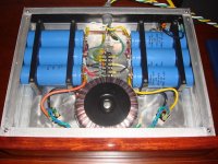
These photographs have posed a question. I am in the process of putting a power supply together in a separate enclosure (box 1) but I hadn’t really thought of the grounding arrangements for the box containing the amp pcbs (box 2).
Should I put in a star ground attached directly to the chassis or leave the chassis unconnected in box 2? Or perhaps connect the two enclosures but not connect the amp ground in box 2 to the chassis.
Regards,
Chris
Should I put in a star ground attached directly to the chassis or leave the chassis unconnected in box 2? Or perhaps connect the two enclosures but not connect the amp ground in box 2 to the chassis.
Regards,
Chris
You have to make the "life critical" decision on whether mains voltage could accidentally appear on any one of the wires in the PSU to amplifier umbilical.
You have to decide on the risk of losing a loved one against the unlikely probability of a worst case mains fault.
I know where I want to be, (not standing giving evidence in a fatal accident inquiry explaining why my decisions led to the fatality).
You have to decide on the risk of losing a loved one against the unlikely probability of a worst case mains fault.
I know where I want to be, (not standing giving evidence in a fatal accident inquiry explaining why my decisions led to the fatality).
- Home
- Amplifiers
- Pass Labs
- Burning Amplifier BA-2