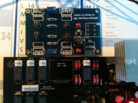
Pics of the build in progress...
As you can see very "high" built. I've planned to cut Mosfet's legs, same operation for 2SK170BL.
Another point concerns the free space between the LT7812 and the right Mosfets sink : find a heatsink that fits !
I'm using 5V relays and the LT gets hot.
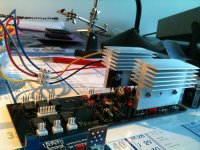
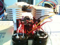
Heatsinks are recycled, they came from old Compaq Proliant PSU, hand saw cutted yesterday.
Do you think it's a good idea to thermally coupling the 2SK170-BL quad ?
As you can see very "high" built. I've planned to cut Mosfet's legs, same operation for 2SK170BL.
Another point concerns the free space between the LT7812 and the right Mosfets sink : find a heatsink that fits !
I'm using 5V relays and the LT gets hot.
Heatsinks are recycled, they came from old Compaq Proliant PSU, hand saw cutted yesterday.
Do you think it's a good idea to thermally coupling the 2SK170-BL quad ?
Attachments
Last edited:
more recommendations for new big blue mez layout
@salas, @ teabag?
can the layout silkscreen be modified to show the polarity marks for polarized caps (e.g. the 4700uf main filters) outside of the component outline circle? otherwise, polarity indication is covered when components are installed.
also is there a provision to add (hopefully 2nd order) lpf (~50kHz) rc filter @ FET gate. i have a problem with my current amp and/or pre (both have >100 kHz BW) where the my highly imperfect source (CD/DVD combo unit) is raising the noise floor and was hoping the new BigBlue could fix that while improving the system resolution.
thx,
Tincanear
Hi regiregi22, me too
Before, I've to power up my LightSpeed too, I'm in lack of 5V PSU.
Could someone point me a scheme for wiring DCB1 and LightSpeed PCB ?
Thanks !!!
I think Alon has a board like that? Maybe he can let you know if he reads.
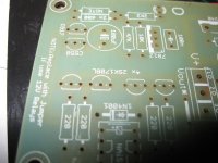
Pics of the build in progress...
As you can see very "high" built. I've planned to cut Mosfet's legs, same operation for 2SK170BL.
Another point concerns the free space between the LT7812 and the right Mosfets sink : find a heatsink that fits !
I'm using 5V relays and the LT gets hot.
Heatsinks are recycled, they came from old Compaq Proliant PSU, hand saw cutted yesterday.
Do you think it's a good idea to thermally coupling the 2SK170-BL quad ?
Bend the LT forward a bit and bolt one sink on it.
") Nothing to really gain by coupling the quad IMHO, its not about a differential amplifier.
Nothing to really gain by coupling the quad IMHO, its not about a differential amplifier.@salas, @ teabag?
can the layout silkscreen be modified to show the polarity marks for polarized caps (e.g. the 4700uf main filters) outside of the component outline circle? otherwise, polarity indication is covered when components are installed.
also is there a provision to add (hopefully 2nd order) lpf (~50kHz) rc filter @ FET gate. i have a problem with my current amp and/or pre (both have >100 kHz BW) where the my highly imperfect source (CD/DVD combo unit) is raising the noise floor and was hoping the new BigBlue could fix that while improving the system resolution.
thx,
Tincanear
But the installed caps still have marks on their jackets I guess. Yes if we ever run any new GB and CRT is accessible we can fix that.
If we cut the bandwidth it sounds lazy. That is why we don't do it with more than 20-25K pot. Why not putting an input filter in the specific amp than to cut all DCB1s?
P.S.
What Blue Mez? Now people want a Blue Mez? Here we go again...
Sorry, Salas, but i've been away from this thread and am a bit confused about the next planned BigBlue pcb. is this hypno (w/o input selection) or mez (relay driven input select)? i don't want to start another debate-- i just want to be able to get the latest & greatest pcb and finally start building up something...
thanks,
tincanear
Last edited:
There are some beefed up Hypnos sending out by Tea these days http://www.diyaudio.com/forums/group-buys/147075-gb-dc-coupled-b1-buffer-shunt-psus-228.html.
I really love those heatsinks, it reassembles some kind of V8 engined car.Pics of the build in progress...
As you can see very "high" built. I've planned to cut Mosfet's legs, same operation for 2SK170BL.
Another point concerns the free space between the LT7812 and the right Mosfets sink : find a heatsink that fits !
I'm using 5V relays and the LT gets hot.
Heatsinks are recycled, they came from old Compaq Proliant PSU, hand saw cutted yesterday.
Do you think it's a good idea to thermally coupling the 2SK170-BL quad ?
Oh, and I don't need a heatsink for the LT7812. Is runs at ambient temp even after some hours turned on. I'm using a 12v relay though.
Posted this on the GB section, this thread is probably more appropriate..
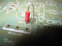
Ok, been stuffing the boards with parts I have available. If we are looking at the board horizontally on top right IRFP240 it looks as if there is an insertion hole missing for one end of the 470r resistor.
Also, the BOM states that there are 4 sk170 matched, where on the board do they go?
BOM does not have a part number for the relay, does anyone happen to have for mouser or digikey, please?
Yes. Near relay. The whole Buffer part (the rest power supply) is after the VOut* seen on right of pic. So all to the left is the buffer, not much to it. The Vout* jumper (white stripe) must be applied in order for Buffer to power up. Otherwise it's just a nice shunt reg supply. There are two other jumpers that need to be done in the power supply as well.
I think Alon has a board like that? Maybe he can let you know if he reads.
Hi Just saw this!!! Sorry Korben69
Its very difficult to explain, but if you havnt already set up your dcb1 with optivol, you could try having a look at page 167 post 1665 There i have posted some pics of my build...the pics are not very good quality, but you can see how the two are connected together. If you cant quite work it out by looking at the pics, then pm me and i will try to explain
On a side note, I would highly recommend powering the optivol, with a Salas Shunt reg set to 5v...i tried quite a few combinations of power supplies for running the optivol and by far the best was removing the power supply section of the optivol board and running direct with 5v salas shunt reg, i did try the salas shunt reg set to 8v as a prereg, and then this went into the optivol 5v supply, but this did not sound as good. Pics to follow.
Alon
Wendell, hope this helps. 470r one stands soldier style.
Relay I used is OMRON Mouser 653-G6H-2-100DC12
Is this the Blue Board Build? they look Green.
Blue Build Thread is
http://www.diyaudio.com/forums/anal...as-hotrodded-blue-dcb1-build.html#post2269475
Thank guys you for your answers
Malka07, I'll send you a PM for my built, your help will be great. Very nice result, I like the "Zen look" !
I use a Mezmerize board not Hypnotize. I'll try a GoldMinireg as PSU for the 5V.
Your pics show that you've wired the LDR Output(L/R) to the Hypno Input(L/R).
How should I proceed with the Pot on the Mezmerize PCB ?
Should I just ignore it ?
sandbasser, the LT7812 gets a little bit hot when using 5v relays : heatsink recommended.
My mistake, the tansformer is 2x15v. 2x12 is a typo. Some Selectronic RCore are oversized as mine, 2x15v gives about 19.5v at the output...
Salas, yes, bending the LT is the right solution. I'll give it a try.
Last edited:
A couple of questions:
The "Blue" Hypnotize BOM specifies a 2x15 transformer while the 'original' Hypnotize-Mezmerize specifies a 2x12. What's different???
Can someone please summarize the pros and cons of the 12v relay vs the 5v relay??
Thanks,
The Blue is geared up towards heavy use so it will be certainly sinked, thus more Vin to Vout created by a higher Tx makes it regulate in more ample margin without caring for some extra dissipation. They will run it up to 1amp some, wait and see...
12V will create less dissipation on its feed components. 5V option is when you can't find 12V cheap or available at a time. Basically there was a sub GB for 5V ones back then so we catered for both. 12V is the natural choice.
- Home
- Amplifiers
- Pass Labs
- Building a symmetrical PSU B1 buffer