Could this LED be used for the relay indicator?
http://www.lumex.com/specs/SSL-LX20R6USBD.pdf
And if so, what value would have to be used instead of the 2k2 resistor?
http://www.lumex.com/specs/SSL-LX20R6USBD.pdf
And if so, what value would have to be used instead of the 2k2 resistor?
That one combination LED says Vfmin-max=10.5-12V, nominal current 20mA, 30mA max. You got 12V at the LED position. Nothing will remain. Thus, no. Don't run it off some higher place that associates with the main rectification either, we don't know what kind of noise it throws.
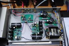
I am sorry but I could not resist the temptation to post this pic of my P2P DCB1 build.
It is using V1 shunts but it will soon be upgraded with a Reflektor pair.
Even now, it sounds better than My Pedja buffer with V12R.
I wish I could have a simple DC detector to add just for safety because my meridian 103 amp does not have any input cap and no DC protection.
Hope those Bourns Vref trimmers do not fail during my listening sessions.
I am having difficulties setting the same DC offset on both channels because the PSU is common to both.... Maybe i should use a separated PSU for each channel")
It is using V1 shunts but it will soon be upgraded with a Reflektor pair.
Even now, it sounds better than My Pedja buffer with V12R.
I wish I could have a simple DC detector to add just for safety because my meridian 103 amp does not have any input cap and no DC protection.
Hope those Bourns Vref trimmers do not fail during my listening sessions.
I am having difficulties setting the same DC offset on both channels because the PSU is common to both.... Maybe i should use a separated PSU for each channel
Attachments
Last edited:
One led lights on power on and dims after the relay closes.
The other led lights up when the relay closes.
I will choose what to use when I finish the case.
I must build the new shunts in the first place and I want to include a DC sensor to open the Relay if it senses more than 2mV on the output.... maybe a mosfet can de used for that purpose.
The other led lights up when the relay closes.
I will choose what to use when I finish the case.
I must build the new shunts in the first place and I want to include a DC sensor to open the Relay if it senses more than 2mV on the output.... maybe a mosfet can de used for that purpose.
That is a mighty ambitious target.open the Relay if it senses more than 2mV on the output.... maybe a mosfet can de used for that purpose.
2mV for how long? 1second, or 10seconds, or 1minute?
20mV for how long? 1millisecond or 10milliseconds or 100milliseconds?
200mV for how long?
Do you see the problem.
You have to decide what the next stages and equipment can tolerate for what period of time. Then design to trigger just in time to protect the equipment.
Hypnotize build
Hi Salas
I have started building a hypnotize board for my line preamp, to be followed by two SSLV1.1 boards for the 5V and gate supply on my Tripath amp.
I am considering using the TO-220 mosfets (as per SSLV1.1) for the Hypnotize as I have these parts already. Is this a good idea? or should I use 240/9240 to preserve voicing etc.
Also, I noticed that two FET resistors on the Hypnotise are now shown as 1R instead of 10R. What is the reason for this change?
Sorry if my questions have been answered elsewhere on the thread.
Don't know, haven't experienced it with different Mosfets than standard. You should look for comparable crss and gfs characteristics to the originals at least for the output ones.
Those resistors are there to be able to sample a voltage drop if tweaking for general use psu or when troubleshooting. Non significant. Made smaller to reserve precious Vbe threshold better.
Those resistors are there to be able to sample a voltage drop if tweaking for general use psu or when troubleshooting. Non significant. Made smaller to reserve precious Vbe threshold better.
Andrew are you showing off your comedic sideThis is an english language Forum.
Moderators should know better.
I know it gave me a chuckle.Many thanks Salas,
You don't know what the original B1 input impedance is do you? I have the original, but want to get the DC version as I am reading everywhere that it's better.
Cheers,
Colin
You don't know what the original B1 input impedance is do you? I have the original, but want to get the DC version as I am reading everywhere that it's better.
Cheers,
Colin
DCB1 is 220k sans pot.
- Home
- Amplifiers
- Pass Labs
- Building a symmetrical PSU B1 buffer