BA-1 pics
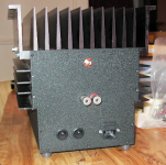
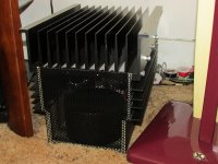
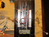
Here's my recently completed SemiSouth BA-1 monoblocks. A pair of matched R100's at the gain position, and matched 240's as current sources in each monoblock. 22.5V rails, 3A bias current... that's the max these heatsinks can take. They are definitely room heaters that happen to make music. Everything point to point wired in the output stage, bias circuit on perfboard. Papa forgot the power on LED so I replaced that zener diode at the voltage divider with a mini CCS string of 3 green LED's and a 2SK117GR (~4 mA) with an RC in front of that... just for more isolation.
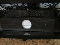
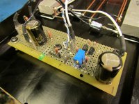
Front end is separate with it's own shunt regulated supply (Salas DCB1 minus the buffer part that I cut off). Sorry for the dark picture, it's all sinister you know... (maybe Darth Vader would approve) The supply is loaded up with a bunch of yellow LED's that glow through the perforated metal top. With my source turned up and paused, I hear nothing with my ear nearly touching the speaker cones so it's all quiet as the grave. The Hammond transformer powering this does have a low level mechanical buzz I'm not happy with, may end up changing that out.
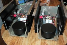
Sound is very good, and getting better as everything settles in. It definitely is better after warming up, also. Will be interesting to see how this compares to the F5 I lived with this last year or so. I'll see if I can round up a couple of internal shots.
Here's my recently completed SemiSouth BA-1 monoblocks. A pair of matched R100's at the gain position, and matched 240's as current sources in each monoblock. 22.5V rails, 3A bias current... that's the max these heatsinks can take. They are definitely room heaters that happen to make music. Everything point to point wired in the output stage, bias circuit on perfboard. Papa forgot the power on LED so I replaced that zener diode at the voltage divider with a mini CCS string of 3 green LED's and a 2SK117GR (~4 mA) with an RC in front of that... just for more isolation.
Front end is separate with it's own shunt regulated supply (Salas DCB1 minus the buffer part that I cut off). Sorry for the dark picture, it's all sinister you know... (maybe Darth Vader would approve) The supply is loaded up with a bunch of yellow LED's that glow through the perforated metal top. With my source turned up and paused, I hear nothing with my ear nearly touching the speaker cones so it's all quiet as the grave. The Hammond transformer powering this does have a low level mechanical buzz I'm not happy with, may end up changing that out.
Sound is very good, and getting better as everything settles in. It definitely is better after warming up, also. Will be interesting to see how this compares to the F5 I lived with this last year or so. I'll see if I can round up a couple of internal shots.
Attachments

update
I might be talking to myself in this thread but anyhow....
After more listening I discovered a problem on certain tracks, centered somewhere around the upper mids / low treble. Just a harsh, static like type of distortion at times. But very noticeable on track 6 of the Stereophile Test CD2, a Flute Sonata, very harsh / grating sound. I've heard this disc many times (every time I change something with my system) and knew I had to try and figure out what was going on.
Searching the forums I found Generg's "BA2 J2 Monster Clone" or something and ZM talked about the LTP current and "letting it bleed" when driving these SS JFETS. Well I tossed out the original voltage divider circuit and built a CCS out of a pair of K170's chosen at 10mA each. 500r pot at the bottom to ground with a 220r resistor in parallel which gives an adjustment range of 0-3V. My parts need about 1.94V or so. 680r's on top to keep the jfet dissipation in check. And I figured "bleeding" 20mA should be more than enough. It completely cured that problem. Need more time on these but things are getting real interesting now...
Attachments
problem
Was going to post a schematic but I've run into a problem. Amp #1 has been stable for several days with the circuit above. Amp #2 was looking good on the bench then suddenly the output offset became unstable during warm-up. As if it's oscillating or something. Out of frustration I've thrown together a two transistor current source with thermally bonded BC556's on a little piece of veroboard. 100r load resistor and a 50r trimmer on top. So again this is setup for ~20mA of current. It looks like figure 6a here: Current Sources, Sinks and Mirrors in Audio Only difference is I've added a .1uF cap emitter to collector of Q3.
If this thing runs stable for several hours at full operating temp I'll throw it back in the system to make sure it still sounds OK. More later....
I'm often using that sort of CCS - ( right one on linked pic)
probably because even I can calculate values for it
brake R4 in two 4K7 , connect their node via 1-10uF to positive rail
also - base resistors of some 330-1K can't harm
probably because even I can calculate values for it
An externally hosted image should be here but it was not working when we last tested it.
brake R4 in two 4K7 , connect their node via 1-10uF to positive rail
also - base resistors of some 330-1K can't harm
Last edited:
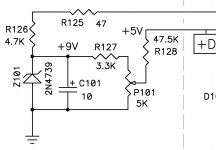
Latest incarnation, and maybe last, of this Semisouth bias circuit ... DN2540 cascode (TO-92's, $1.24 @ Mouser) per Walt Jung's Current Regulator's Revisited article in AudioXpress. Rload=100r, Rset=200r trimmer, 300r carbon gate stoppers right at gate pins of the 2540's. 8k series resistor from the top of Rload to the SS gate bus bar, 220r gate stoppers at the gate pins of the power JFETs.
Maybe what I've done here is absolute overkill silly-ness, but it's simple and cheap, and sounds fantastic. Along with a couple of other small changes elsewhere, this is the best sound I've achieved yet. I'm not missing that F5... (PV1.4 = 1.26 X 10⁴ ???)
Maybe what I've done here is absolute overkill silly-ness, but it's simple and cheap, and sounds fantastic. Along with a couple of other small changes elsewhere, this is the best sound I've achieved yet. I'm not missing that F5... (PV1.4 = 1.26 X 10⁴ ???
)Latest incarnation, and maybe last, of this Semisouth bias circuit ... DN2540 cascode (TO-92's, $1.24 @ Mouser) per Walt Jung's Current Regulator's Revisited article in AudioXpress. Rload=100r, Rset=200r trimmer, 300r carbon gate stoppers right at gate pins of the 2540's. 8k series resistor from the top of Rload to the SS gate bus bar, 220r gate stoppers at the gate pins of the power JFETs.
Maybe what I've done here is absolute overkill silly-ness, but it's simple and cheap, and sounds fantastic. Along with a couple of other small changes elsewhere, this is the best sound I've achieved yet. I'm not missing that F5... (PV1.4 = 1.26 X 10⁴ ???
I agree with ZM, can you show the current schematic? It would make it a lot easier to follow along.
They are pure heat. This is a Burning Amp.
You will get a lot more efficiency out of BA#2, which is push-pull
instead of single-ended/constant current source.
If you want more efficiency out of the all-N channel output stages,
we will expect to be doubling the efficiency in a later version.
I'm just re-reading this thread. Did the higher efficiency all N channel see the light of day?
The only big difference between what I've done and the original - is replacing the bias circuit for the upper power FETS with the Cascode Current Source from Walt's article here: http://www.waltjung.org/PDFs/Sources_101_Letter_Revisit_0409.pdf
I used the circuit on the left of Figure 1. My opinion is this is better suited to the SemiSouth R100 JFETS that I wanted to use.
I made no changes to the front end circuit. And no changes to the bias circuit for the bottom power FETS (still IRFP240's). And my output stage is "2-deep" rather than "6-deep" as shown in the original article. I now use an Aleph J (semi Babelfish) in place of the BA-1 and am enjoying it very much also.
The only big difference between what I've done and the original - is replacing the bias circuit for the upper power FETS with the Cascode Current Source from Walt's article here: http://www.waltjung.org/PDFs/Sources_101_Letter_Revisit_0409.pdf
I used the circuit on the left of Figure 1. My opinion is this is better suited to the SemiSouth R100 JFETS that I wanted to use.
I made no changes to the front end circuit. And no changes to the bias circuit for the bottom power FETS (still IRFP240's). And my output stage is "2-deep" rather than "6-deep" as shown in the original article. I now use an Aleph J (semi Babelfish) in place of the BA-1 and am enjoying it very much also.
I think your ideas are cool, I just want to make sure I have them right for a try.
You gave up on the 2SK170 CS and the green LEDs with the 2SK117? Is the 240 gone in favor of the Jung Cascode? Even a hand drawn version of your final would be helpful. If not possible, the total changes are:
Remove the IRFP240 completely, add two DN2450 (Cascoded) and Rload=100r, Rset=200r trimmer, 300r carbon gate stoppers right at gate pins of the 2540's. 8k series resistor from the top of Rload to the SS gate bus bar, 220r gate stoppers at the gate pins of the power JFETs?
No other mods (ie my question about the 2SK170 CS and the green LEDs with the 2SK117)?
TIA
Last edited:
I think your ideas are cool, I just want to make sure I have them right for a try.
You gave up on the 2SK170 CS and the green LEDs with the 2SK117? Even a hand drawn version of your final would be helpful. If not possible, the total changes are:
You added two DN2450 (Cascoded) and Rload=100r, Rset=200r trimmer, 300r carbon gate stoppers right at gate pins of the 2540's. 8k series resistor from the top of Rload to the SS gate bus bar, 220r gate stoppers at the gate pins of the power JFETs?
No other mods (ie my question about the 2SK170 CS and the green LEDs with the 2SK117)?
TIA
I now realize you keep the 240 as one output, but I could benefit from a schematic.
I'm just not good enough to follow what's still in and what's been replaced. I'm not sure if you put the SS or the IRFP240 at the top or bottom. I realize you mentioned the words, I just want to make sure I see the top the same as you.
Working from the NP schematic: did you replace Z201, R213, P202, C209 and R214 and use that to bias the IRFP240 or the SS (top of the circuit), or did you replace R216, R217 C207, Q204, R219, R218, and use the Jung circuit to bias the IRFP240 or the SSR100 (bottom of the circuit)?
Last edited:
I only changed this part of the circuit.. replaced with that circuit I linked to. Those previous iterations with the K170's and LED's and all that were just me experimenting.
This circuit establishes the bias voltage at the gates of the SS R100's. The 8k series resistor I refer to would be at R128.
SemiSouth on top, 240's on bottom. And by "2 deep", I mean I have a matched pair of R100's on top, and a matched pair of 240's on the bottom. My source resistors are .34 ohms (pair of .68 ohm resistors in parallel at each location).
I hope this clears up the confusion. Just be careful and make sure you understand what's going on here if you were going to try this, I wouldn't want to see someone blow their $$$$ JFETS.
Attachments
I only changed this part of the circuit.. replaced with that circuit I linked to. Those previous iterations with the K170's and LED's and all that were just me experimenting.
This circuit establishes the bias voltage at the gates of the SS R100's. The 8k series resistor I refer to would be at R128.
SemiSouth on top, 240's on bottom. And by "2 deep", I mean I have a matched pair of R100's on top, and a matched pair of 240's on the bottom. My source resistors are .34 ohms (pair of .68 ohm resistors in parallel at each location).
I hope this clears up the confusion. Just be careful and make sure you understand what's going on here if you were going to try this, I wouldn't want to see someone blow their $$$$ JFETS.
Thanks.
I'm just getting back to finishing my J2 clone. Then I'm going to give BA1 a shot. I read a fair amount about the CCS and I'd like to try the R100s in the BA1. I'm hoping to compare the BA1 with SS against J2 and SIT.
- Home
- Amplifiers
- Pass Labs
- Burning Amplifier BA-1