Hang in there, I should be able to get mine built and tested soon. My local situation has played out, and I should have some decent time to give to this.
BTW, I also have a 3562A here, and me thinks there is a problem in your setup. The Frequency response plot should be a ruler flat straight line at high frequencies. Do you have the user guide for it?
I have a built B1 for comparison as well. No oscillation so far.
Bob
BTW, I also have a 3562A here, and me thinks there is a problem in your setup. The Frequency response plot should be a ruler flat straight line at high frequencies. Do you have the user guide for it?
I have a built B1 for comparison as well. No oscillation so far.
Bob
> +/-9V is the supply voltage I used for checking to see if an increase in supply voltage would help anything. This is when I noted an increase in susceptibility to oscillation.
That I understood, but with proper decoupling, oscillation is not a problem, and you might probably see less distortion for the same voltage swing, because of more headroom in Vds.
The same applies to the reduction is DC offset. Best distortion cancellation will occur when the upper and lower JFETs see the same Vds. And I have given you hints how to adjust that, given your imperfect matching.
Patrick
http://www.diyaudio.com/forums/showthread.php?postid=1861675#post1861675
For those who would not just take my word, someome has taken the plunge and found the BF862 "sounding better than the 2SK170 in the same topology".
Patrick
For those who would not just take my word, someome has taken the plunge and found the BF862 "sounding better than the 2SK170 in the same topology".
Patrick
If you want to use opamps that you can use one of these :
http://ntur.lib.ntu.edu.tw/retrieve/173979/02.pdf
http://dspace.thapar.edu:8080/dspace/bitstream/123456789/113/1/6040411.pdf
No idea how to do a differential amp without feedback in a source follower.
Patrick
http://ntur.lib.ntu.edu.tw/retrieve/173979/02.pdf
http://dspace.thapar.edu:8080/dspace/bitstream/123456789/113/1/6040411.pdf
No idea how to do a differential amp without feedback in a source follower.
Patrick
sorry to resurrect a thread from so long ago,
if we wanted to build a complete pre amp based around this, in the style of the B1,
what else is recommended, local decoupling- no problem.
how about recommended rail voltage?
would the BF862 work dropped straight into the B1 circuit?
if we wanted to build a complete pre amp based around this, in the style of the B1,
what else is recommended, local decoupling- no problem.
how about recommended rail voltage?
would the BF862 work dropped straight into the B1 circuit?
sorry to resurrect a thread from so long ago,
if we wanted to build a complete pre amp based around this, in the style of the B1,
what else is recommended, local decoupling- no problem.
how about recommended rail voltage?
would the BF862 work dropped straight into the B1 circuit?
Check this thread http://www.diyaudio.com/forums/pass-labs/146310-bf862-preamp.html#post1861675 and you will find one version using BF862 with discrete shunt regulators. Juma may be of help.
See :
http://www.diyaudio.com/forums/group-buys/216669-joachim-gerhard-filter-buffer-es9022.html
for an updated, higher-performance, cascoded BF862 buffer.
Patrick
http://www.diyaudio.com/forums/group-buys/216669-joachim-gerhard-filter-buffer-es9022.html
for an updated, higher-performance, cascoded BF862 buffer.
Patrick
Not on a chip but same bits n pieces
I've always wanted to try this buffer. I dont know why it hasnt picked up more traction but there's a sale at the pcb house and a customer wants a buffer. Sounds like a good time to see what I've been missing.
The board is 132mmx59mm. It stacks on top of my attenuator boards and therefore the size and a few restrictions.
I am posting my first shot at laying this out and already there is a change not shown in the pic. Patrick suggested to use 0805 200R gate stoppers and I was using 1/4w leaded resistors as I love the sound of RNC55 and RLR07 from Vishay/Dale. So I will have to adapt to the 0805. A bit of moving around from what I've got so far. If youre looking for outputs, theyre not there yet.
I'm using LT1963A as positive and negative regs as output voltage from a dual secondary transformer fed supply. Transformer, rectification and a few smoothing caps are off board. I am using the regs in adjustable mode as I saw there were a few comments in the thread regarding voltage maybe causing changes in THD and oscillations a member was having. The board is only labeled for me so many of the components arent labeled. If you're interested in the supply the large SMT caps are 220uf 20V Oscons, large ceramics are X7R 10uf and then at the output to ground pins of the regs there is a .1uf that seems more necessary than I had suspected. The 4 caps in the center are 1000uf 25V Nichicon KW. JFETS and resistors in the buffer circuit in the center are labeled according to Patrick's schematic with the addition of R5 to ground which will probably be 200k to 1M. R5 is shown but you cant see it connect to ground as I have the ground layer turned off so you can see the rest of the circuit. Anywhere you see a bunch of tiny holes, thats a connection from the top plane to the ground plane. I might show the whole schematic later but its not on paper yet. Well, here is the board:
Attachments
Last edited:
If you could place inputs together at one side and do the same for the outputs wiring will be less messy and input/output and power supply wires won't cross. If you add pads for rectifier diodes you can reuse the design another time as it will be more versatile. Just leave the parts you won't use unpopulated for this particular customer. On the risk of being called a "repeatist": I would definitely use a very tiny muting relay that shorts the output to GND at power up for a few seconds as you know what customers do... just a day after you told them not to do so they first switch on the power amp and then the preamp/buffer... This circuit does give a plop when powered on. Not a good combination with a hefty power amp (probably/likely with no volume control at its inputs). You can use the tiniest of micro relays for this task and they only use a few tens of mA. Small and cheap addition that can save the customers woofers.
It won't hurt to use CLC or CRC filtering before the regs.
It won't hurt to use CLC or CRC filtering before the regs.
Last edited:
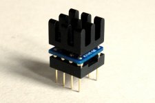
Dual JFET Follower Buffer on DIP8
A few months ago in November, we did a modular active crossover for various speakers.
https://www.diyaudio.com/forums/ana...ve-crossover-filter-solution.html#post5591077
This renews the need for a discrete JFET Follower buffer, but this time 2 channels on a DIP8 footprint.
In October 2018, we also compared the distortion of NJFET followers using different devices.
https://www.diyaudio.com/forums/pas...source-follower-applications.html#post5583280
This leads us to design and build a new module using 4 pairs of matched Toshiba SMD N-JFETs.
Total current consumption is 15mA.
The heatsink is not strictly necessary, but it helps with thermal tracking.
DC offsets can be trimmed with source resistors.
The prototype shown here has offsets 0f 0.9mV and 1.3mV, and are stable over time.
So no need to use opamps in unity gain in those active crossovers.
")
Patrick
.
A few months ago in November, we did a modular active crossover for various speakers.
https://www.diyaudio.com/forums/ana...ve-crossover-filter-solution.html#post5591077
This renews the need for a discrete JFET Follower buffer, but this time 2 channels on a DIP8 footprint.
In October 2018, we also compared the distortion of NJFET followers using different devices.
https://www.diyaudio.com/forums/pas...source-follower-applications.html#post5583280
This leads us to design and build a new module using 4 pairs of matched Toshiba SMD N-JFETs.
Total current consumption is 15mA.
The heatsink is not strictly necessary, but it helps with thermal tracking.
DC offsets can be trimmed with source resistors.
The prototype shown here has offsets 0f 0.9mV and 1.3mV, and are stable over time.
So no need to use opamps in unity gain in those active crossovers.
Patrick
.
Attachments
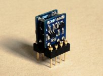
Dual Black Forest Buffer II on DIP8
The Dual JFET buffer above is happy with 10k load or so.
But what if we want to drive a lower impedance.
Of course the Black Forest Buffer will easily drive 600R.
The diyAudio First Watt M2x
But won't fit 2 of them on DIP8.
So this is a mini-version.
Bias per buffer is 10mA. DC offset < 2mV with matched devices, without trimming.
Bandwidth 1MHz -3dB. Clean square waves up to +/-3V, which is perfect for line level.
It likes some load. Anything from 2k to 5k is fine.
Cheers,
Patrick
.
Attachments
- Home
- Amplifiers
- Pass Labs
- B1-Turbo on a Chip