I etched a small PCB with 3 pads and wired them accordingly.
But you can do that esily also with a universal strip board. Just cut one of the strips to make 2 separate tracks for D & S, and use the neighbouring strip for gate.
Then hold the JFET down with a fine tweezer on the top of the SOT23 package in position on the PCB before applying voltage. Put a current limit on your power supply at say 30mA. I use 9V myself for matching.
As mentioned before, I shall make matched FETs available later when there is sufficient interest. The pioneers would have to suffer, as usual.

Patrick
But you can do that esily also with a universal strip board. Just cut one of the strips to make 2 separate tracks for D & S, and use the neighbouring strip for gate.
Then hold the JFET down with a fine tweezer on the top of the SOT23 package in position on the PCB before applying voltage. Put a current limit on your power supply at say 30mA. I use 9V myself for matching.
As mentioned before, I shall make matched FETs available later when there is sufficient interest. The pioneers would have to suffer, as usual.
Patrick
Just wanted to check in and report my boards finally arrived a few weeks ago. I have also ordered parts, and will be building and listening soon if all goes well.
Last weekend I built a BF862 matching rig. I cut two strips of adhesive backed copper and then soldered wires to the copper strips. I can post a picture if needed to "splain" better.
I hold the chips down with a plastic tool and count to 40 seconds with 10V applied. I am seeing parts well centered around 13ma Idss, with outliers at 12 and 14ma. Once measured, I tape the parts to copper foil with a part number and reading. These things are pretty hardy.
Bob
BFNY said:Last weekend I built a BF862 matching rig. I cut two strips of adhesive backed copper and then soldered wires to the copper strips. I can post a picture if needed to "splain" better.
Please do... i have all the parts just waiting for my electronics guy to get back from a visit (unexpectedly extended) to his mom's
dave
The US Post is rEEEEEally fast !!
I essentially did the same for matching, only with a custom etched PCB.
The Idss varies from batch to batch. The first 2 batches I had were all around 17mA +/- 2mA. The second batch varied between 12 and 16mA. So you are lucky in a way (or unlucky if your circuit would have required 16mA Idss).
At least there is some progress.
Meanwhile I have a dual version and a mixed version (1 DABF862 + 1 SOIC Opamp of any brand) in a single DIP8 footprint already finished on the drawing board. Just need some time to etch, solder and test. I now have all versions covered.

Patrick
I essentially did the same for matching, only with a custom etched PCB.
The Idss varies from batch to batch. The first 2 batches I had were all around 17mA +/- 2mA. The second batch varied between 12 and 16mA. So you are lucky in a way (or unlucky if your circuit would have required 16mA Idss).
At least there is some progress.
Meanwhile I have a dual version and a mixed version (1 DABF862 + 1 SOIC Opamp of any brand) in a single DIP8 footprint already finished on the drawing board. Just need some time to etch, solder and test. I now have all versions covered.
Patrick
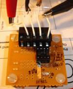
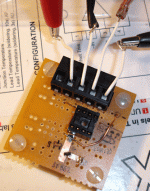
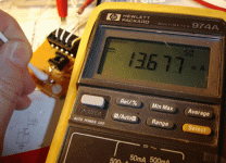
The two center leads go to the HP 974A Multimeter, set for a 50 ma current range. This meter has 4.5 digits resolution, and was *not* an inexpensive model.
The two outer leads go to the + (red) and - (Black) leads of the 10V power supply. This HP supply is current limited 250 ma
This shows the BF862 in place and ready for testing.
The two outer leads go to the + (red) and - (Black) leads of the 10V power supply. This HP supply is current limited 250 ma
This shows the BF862 in place and ready for testing.
Attachments
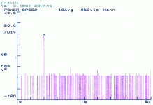
Daniel came home for the weekend and put ours together. Here is a scan of the distortion plot. He'll drop in with comments.
He has to go back and finish fixing his mom's car, but when he gets back, we'll use these as buffers in a PLLXO for Tysen and have a listen.
dave
He has to go back and finish fixing his mom's car, but when he gets back, we'll use these as buffers in a PLLXO for Tysen and have a listen.
dave
Attachments
My mom's car? It's mine 
I have put both boards together with some reasonably matched JFETS and taken quick measurements.
I will have to report back with details at a later date as my time is tight right now.
The distortion plot above shows the fundamental 1kHz at -3dBV or so, and the harmonics at -61 and -66 respectively.
Frequency response at a glance was happily pushing toward the early MHz, but I will need to put this through the analyzer to see what we get later.
I will measure some other things later on as well.
I must note that this circuit is highly prone to oscillation if there is too much inductance in the power supply rails. (I tested this empirically but by accident at first).
More to follow and a listening impression by the lot of us.
Cheers
> I must note that this circuit is highly prone to oscillation if there is too much inductance in the power supply rails. (I tested this empirically but by accident at first).
I have to say this is NOT my experience.
In my test setup, I use standard lab supplies with long wires (1m). On top of that, the package is connected to a small PCB via (Sub-D) pins & sockets which are at least 15mm long. All these without any local power rail decoupling caps. I have also used loads from 200 ohm to 1M, and as far as I can tell from my 100MHz scope, I cannot see any oscillation. And I cannot imagine a more inductance supply in real applications (where you will almost certainly have local PSU decoupling caps within 20mm).
Maybe you have RF pick-up at the input ..... ??
The bandwidth is certainly higher than what I can measure (limited by my functions generator). But that is no surprise.
Patrick
PS If you wish to do a direct comparison to the B1 using 2SK170s, then the test should be carried out under similar conditions :
http://www.firstwatt.com/downloads/B1 Buffer Preamp.pdf
Amongst others 15000uF for the rails, 1V at 1kHz, say 10k load.
As to the distortion levels, the values you obtained are similar to mine :
http://www.diyaudio.com/forums/showthread.php?postid=1774459#post1774459
However, as you can see in Post #11, while the output distortion for 2nd & 3rd are around -60dB or just below, most of these actually originate from the signal generator, in my case at least. The difference between the green and the cyan curves is what comes from the follower circuit itself.
That is why I always measure both input and output signals, as hobbyists signal sources are no comparison to professional equipment. In the ideal world, the green plot in Post 11 should just be one spike with no width at 1kHz, and -infinite dB on the rest of the frequency spectrum.
Patrick
The follower broke into high frequency oscillation during negative portions of the cycle on a 1kHz sine wave at about 3V peak.
Followers driven from low source impedances are known to have oscillation problems in some cases.
I will try to determine more about the situation later.
This article brings up the details on the oscillation problem and I've seen it in many circuits involving followers with capacitive loads and drive from low impedance sources.
http://www.analogzone.com/col_1017.pdf
I had the B1 board connected to a benchtop regulated power supply on a length of twisted pair removed from a cat5 cable. The input was biased using a pair of 10k resistors from V+ to ground as a voltage divider and the input capacitively coupled (function generator through 100nF film cap). Output was connected to nothing but the probe leading to the Tek scope. (There was a scope probe also on the input.)
When the board was bypassed with a 100nF film capacitor directly across its power connections, the oscillations disappeared and the circuit became quite stable even into the long length of RG56 coax with which I later loaded it for further testing.
I will write back with more investigation later.
> When the board was bypassed with a 100nF film capacitor directly across its power connections, the oscillations disappeared and the circuit became quite stable
I would have expected that level of power supply bypass as minimum in any practical application, don't you think ?
Patrick
I would have expected that level of power supply bypass as minimum in any practical application, don't you think ?
Patrick
- Home
- Amplifiers
- Pass Labs
- B1-Turbo on a Chip


