I am building the A5 monobloc. The sound from one channel is muffled and the other no sound at all. The muffled channel stats as follow :
R 11 = 5.32v
Z5 = 9.3v
Q5 between C and E = 4.67v
R 14 = 4.38v
R64 = 0.713v
R65 = 0.621v
R66 = 0.688v
Q18 between G and S =3.65v
Q19 between G and S =3.73v
Q20 between G and S =3.67v
R28 = 0.633v
R29 = 0.901v
R30 = 0.646v
Q6 between G and S =4.04v
Q7 between G and S =3.67v
Q8 between G and S =4.01v
R22 = 14.1mv
R23 = 13.8mv
R24 = 13.8mv
R25 = 14.3mv
Output = 2.4mv
Can anyone help? Thanks.
The bad channel
Readings from the channel that produces no sound and the speaker cone moves in when the power is switch on :
Z5 = 9.03v
R11 = 5.09v
R14 = 4.65v
Q5 C to E = 4.61v
R22-25 = 0
R28 = 0.629v
R29 = 0.744v
R30 = 0.601v
R18 = 0.684v
R19 = 0.638
R20 = 0.655v
Q6 from D to S = 32.7v
Q7 from D to S = 32.62v
Q8 from D to S = 32.74v
Q18 from D to S = 33.3v
Q19 from D to S = 33.31v
Q20 from D to S = 33.27v
Output = -24.0mv
Why do I get a negative reading for the output?
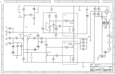
I can't post the whole service manual as it is too large. But you can download here http://vidar.hallais.no/media/download_gallery/Aleph%205%20(60w).pdf
Thanks
Thanks
It looks close, everything is biasing up OK. The only thing I question is the voltage across R28-30 and 52-54.The cone movement is normal unless it's staying in. Check out your grounding to the power supply and your input wiring and connections. 24mv isn't terrible for output offset.
Bill
Bill
R28-30 on the schematic are grid stoppers, 221 ohm. The output fets are biased around 20W each, no problem unless the heatsinks cant handle it.
You have .9xx V for R29 on one channel, check which resistor you actually mean. If that's a source resistor that fet is way off spec.
Bill
You have .9xx V for R29 on one channel, check which resistor you actually mean. If that's a source resistor that fet is way off spec.
Bill
For the channel that produce no sound :
R64 = 0.684v
R65 = 0.638v
R66 = 0.665v
R40 = 0.629v
R41 = 0.744v
R42 = 0.601v
But for the R29 - 220 ohm which feeds the Fet of the R41, I am using a metal film 220 ohm resistor. The rest are ceramic as the supplier is out of stock for the ceramic ones. Should I change all to metal films? Could this explain why I got a higher reading on R41?
The grid stoppers shouldn't affect your bias, there is only two explainations for the differing voltages across your source resistors. Either the resistors values are off or the fets arent matched, or both. The amp should still work though.
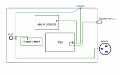
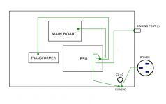
Your grounding scheme isn't exactly right, the AC power ground should go directly to the chassis. The transformer and all circuit grounds should go directly to the PSU, then connect the thermister between the chassis ground and the PSU ground.
Witout the speakers connected, recheck the DC at the output, 24mv wont move a speaker cone much at all.
I don't want to sound negative but don't you think you would be better off starting with a proven professionally made set of boards such as what is available from chipamps.com. I'm sure they would be able to ship them overseas to you.
Troubleshooting an unknown unit over the internet is very difficult at best. You need to apply a signal to the input and follow it and figure out where it's going. Check out the current limiter circuitry and see if its operating normally.
Bill
Output without the speaker is now 30.4mv. I resoldered the binding post. The pcb design was downloaded from mark Finnis site. I just make some changes to suit my chassis, mainly making it bigger and repositioned the fets resistors position. I brought the matched fets from a guy in Germany. I am aware that some people are selling the boards but I have had some bad experience buying things over the net. Unless they are able to provide me with shipping tracking number and insurance, I will buy. Thanks Bill, I really appreciate your help.
Positive or negative on offset does not matter as long as it is a small value. 30mv is within specs but it would be nice if it were lower, I wouldn't lose any sleep over it though.
If R41 is indeed a 1 ohm resistor then that fet is passing 40% more current than the rest of them. Something ain't right!
You're grounding scheme is correct if the thermister is installed between the PSU and the chassis, it's hard to tell on your drawing.
Alephs do have a small turn on thump, but it shouldn't be severe.
I can't comment on a turn off thump, I dont have one, that might be the product of your renegade fet.
Bill
- Status
- This old topic is closed. If you want to reopen this topic, contact a moderator using the "Report Post" button.
- Home
- Amplifiers
- Pass Labs
- Aleph 5 problem 2