No need.
Just make sure your Zener diode can take the power.
Patrick
They're 1W zeners, so should be fine.
Thanks!
Nigel
I used a string of leds and it needed the 5mA - dunno if sounded any different - looked "kool" and left them in as "A'phool" example!
Taylored variation has a slightly different sound (bit softer but more detail) to the basic cct - quite noticeable on the k701 phones and bigger difference on the Bayers (higher R load, perhaps)
'evening Patrick.
Taylored variation has a slightly different sound (bit softer but more detail) to the basic cct - quite noticeable on the k701 phones and bigger difference on the Bayers (higher R load, perhaps)
'evening Patrick.
wow, yet another headamp on my shortlist..... well there are really only 3 on there. this and the JFET dispre at the top
funny I never read this far before, although I have used this thread as a jumping board several times while researching simple followers to turn dac IV's into headamp outputs, but your work in the pass Zen Jfet IV thread has me intrigued and my DIY confidence grown, so I looked with new eyes.
was there ever a PCB made for the X version? and if so where do I sign? I dont care how polished or not it is. all my headphones are recabled balanced and although i'm not beyond building 2 amps that double as bar heaters for this purpose; I prefer a fully Diff amp. so its either PERF plus massive sink here I come, or hopefully PCB of some sort.
some will know that I like my custom IEMs very much (JH13) and they are my preferred headphone, I also have partially markl (DIY) modded tasmanian blackwood Denon D2000, Senn HD600 and have my eye on some HF2's
From what I gather it will work well with the HF2, denons and senns, which is excellent but the amp should work with the customs best (28ohms). series resistance and the customs dont play well together due to the 3 way crossover; will I be able to build a suitable (preferably DC coupled) amp with any of the many variants I can find here? will the X work as is with some tweaking of the bias points?
I see the X uses CRD's, which I have a few of, plus some LSK170 and 2sk170 (both 8ma IDSS matched) sound like they will go a long way,
I wonder if any of the other CCS's would perform better than the CRDs? subjectively and in your opinion that is, I dont expect you to advise me of what might sound best to me, because I totally agree only I can find this out for myself once and for all.
thanks for putting this novel design out there, I hope to join the club soon enough.
Last edited:
I have not built the X'ed circuit, as I am too lazy to rewire.
If you want the simplest balanced version (and I have built and published photos of one), then you should consider building a circlotron follower.
You can just use 2SK170GR or BL for the CRD. There is no magic. I just used what I had. 2SK170 is probably even lower noise.
This thing will drive your 28 ohm phone with real ease.
Patrick
OK thanks Patrick, I wondered why I hadnt seen anything, SE circuits still do seem to drive this place and while balanced versions are often mentioned, very few actually make it to fruition. from your posts it seemed to me that you favor them also? I have only heard of the circlotron in passing, but will definitely have a search for your posts.
you hit the nail right on the head though; I already have a couple of rather more complex designs built that drive my other cans just fine

and really my IV does a pretty decent job of driving the JH as is, but sometimes I wish for a simpler discrete circuit and a bit more current headroom for them and low output Z/best damping (as with grados) is of the utmost, so simple followers arent always appropriate.
the JH are surprisingly difficult headphones to drive well and suck current like nobody's business, as at some frequencies they present well under 10 ohms, while the multiple drivers (6 per ear) are a reasonably complex load.
thanks again
Jeremy
you hit the nail right on the head though; I already have a couple of rather more complex designs built that drive my other cans just fine
and really my IV does a pretty decent job of driving the JH as is, but sometimes I wish for a simpler discrete circuit and a bit more current headroom for them and low output Z/best damping (as with grados) is of the utmost, so simple followers arent always appropriate.
the JH are surprisingly difficult headphones to drive well and suck current like nobody's business, as at some frequencies they present well under 10 ohms, while the multiple drivers (6 per ear) are a reasonably complex load.
thanks again
Jeremy
Attachments
Last edited:
The DAO has an output impedance of about 4 ohms and a Class A output current of over 0.4A. It is totally happy with load down to 25R or so. You need to go to a power amp circuit to beat that.
Patrick
Patrick
OK thanks Patrick, I wondered why I hadnt seen anything, SE circuits still do seem to drive this place and while balanced versions are often mentioned, very few actually make it to fruition.
Here's one that's well on its way (performs great on the bench, hoping to do some listening this weekend).
The input transformers, in addition to providing galvanic isolation, also provide all of the signal amplification (i.e. voltage gain, in this case, a gain of about 5). They also allow both balanced and unbalanced sources to be used without any switching or added circuitry.
The output buffer uses a pair of discrete BJT darlingtons in a balanced, choke loaded Gilson follower arrangement. A bifilar line output transformer is used to create a center tapped choke. Because the idle current is flowing in each half in opposite directions, the magnetic fields cancel and there is no net magnetization of the core.
Q101/Q102 and Q103/Q104 are matched pairs. P102 allows for what little offset there may be to be zeroed out.
It's powered by a single 24 volt supply, using a TLE2426 "rail splitter" to bias the output stage. The DCR of the center tapped choke (about 40 ohms per side) along with the 10 ohms of the offset trimmer are used to set the idle current which is around 250mA.
It has two drawbacks.
One, using 1:5 microphone transformers as in this implementation, it puts some restrictions on the source driving it. It should have an output impedance of 300 ohms or less, it can't have a peak output of more than about 4 volts, and it needs to be able to drive a 3k ohm load.
Two, because of all the iron (hence Ironhorse), it's not cheap.
An externally hosted image should be here but it was not working when we last tested it.
se
Last edited:
@ Patrick, I found pics of your balanced circlotron, but could not for the life of me find the circuit. can you link me please? very cool DIY PCB and assembly mate, aside from the sinking and PSU, the size is quite compact and the case will be fine for sinking, so will fit quite well.
its this right??
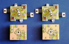
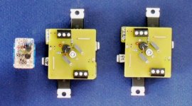
@ Steve Eddy
thanks so much for the info Steve , not the smallest of circuits either due to the iron and I have limited space to work with. i'll keep an eye on your movement on it, need to make a decision pretty soon or just build al of them and see which works out best. I havent ruled out housing it in a separate enclosure though.
is this what they call a 'virtual ground' hehe, didnt think i'd ever see you use something of this nature
I dont have any issues with output Z, this is near zero, but output voltage of the IV may be an issue in its current form. I would have to lower the gain.
the IV is in flux at the moment though, I have owens D1 mosfet, an opamp based IV with OPA1632 and soon will have a discrete JFET version (sans buffer) and probably will give the pass Zen JFET IV a go too. all will pass the output Z test, and i'm sure I can make them fit the 4v spec too.
thanks again.
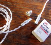
BTW I think you would approve of my use of connectors lately, the whole headphone rig (both home gear and the transportable below) is set up with lemo 4 and 6 pin minisnap series. They are excellent connectors; not cheap, but very nice materials, great build quality, locking and tiny. far superior to mini XLR IMO, but you do pay the price for them, still nothing to pay compared to high end XLR prices
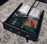
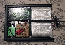
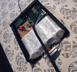
these are all early prototype pics of the portable buffalo II dac/amp, with lemo 4 pin on a JH13 cable. the portable buff also sports a 50 ohms lemo mini BNC, I changed the spdif termination R's and the spdif line driver's input transformer, so its all good.
battery here is a 4 cell 14v 2200mah LiFePo4 pack, but I also have a 6 cell 1100mah. using 7 pin amphenol Hybrid DSUB high current connector for the balance tap and fast charging connector so each cell can be accessed separately by the charger
its this right??


@ Steve Eddy
thanks so much for the info Steve
 , not the smallest of circuits either due to the iron and I have limited space to work with. i'll keep an eye on your movement on it, need to make a decision pretty soon or just build al of them and see which works out best. I havent ruled out housing it in a separate enclosure though.
It's powered by a single 24 volt supply, using a TLE2426 "rail splitter" to bias the output stage. The DCR of the center tapped choke (about 40 ohms per side) along with the 10 ohms of the offset trimmer are used to set the idle current which is around 250mA.
is this what they call a 'virtual ground' hehe, didnt think i'd ever see you use something of this nature

I dont have any issues with output Z, this is near zero, but output voltage of the IV may be an issue in its current form. I would have to lower the gain.
the IV is in flux at the moment though, I have owens D1 mosfet, an opamp based IV with OPA1632 and soon will have a discrete JFET version (sans buffer) and probably will give the pass Zen JFET IV a go too. all will pass the output Z test, and i'm sure I can make them fit the 4v spec too.
thanks again.
BTW I think you would approve of my use of connectors lately, the whole headphone rig (both home gear and the transportable below) is set up with lemo 4 and 6 pin minisnap series. They are excellent connectors; not cheap, but very nice materials, great build quality, locking and tiny. far superior to mini XLR IMO, but you do pay the price for them, still nothing to pay compared to high end XLR prices
these are all early prototype pics of the portable buffalo II dac/amp, with lemo 4 pin on a JH13 cable. the portable buff also sports a 50 ohms lemo mini BNC, I changed the spdif termination R's and the spdif line driver's input transformer, so its all good.
battery here is a 4 cell 14v 2200mah LiFePo4 pack, but I also have a 6 cell 1100mah. using 7 pin amphenol Hybrid DSUB high current connector for the balance tap and fast charging connector so each cell can be accessed separately by the charger


thanks so much for the info Steve, not the smallest of circuits either due to the iron and I have limited space to work with.
Well, yeah, there is that. The trannies take up about 13 square inches of floorspace.
i'll keep an eye on your movement on it, need to make a decision pretty soon or just build al of them and see which works out best.
If you have the resources to do that, it would certainly be the best option. No wondering down the road whether you might have preferred some other option.
is this what they call a 'virtual ground' hehe, didnt think i'd ever see you use something of this nature
Hehehe. I don't know that I'd call it a virtual ground per se. I tend to look at it as just a simple bias voltage seeing as there's no signal current flowing through it. Though it does provide a DC path to ground for the BJT base currents. But if it used FETs instead, there wouldn't be even that. So... I dunno.
Now, the one thing you definitely will never see me use is a third channel "active ground." 😀
I dont have any issues with output Z, this is near zero, but output voltage of the IV may be an issue in its current form. I would have to lower the gain.
Hmmm. Well, depending on what the output voltage is, there may be another solution.
If the output voltage is sufficient for the headphones and all you need is volume control and output buffering, you could replace the 1:5's with a pair of 1:1's. If wired in series, and using a pair of CMLI-15/15B's and changing the attenuator values to 10k, then your maximum input level goes up to 15 volts RMS.
Or you could wire the primaries in opposite polarity parallel, use 25k attenuators and you'd get a bit under 6dB of voltage gain and maximum input would be around 7 volts RMS.
the IV is in flux at the moment though, I have owens D1 mosfet, an opamp based IV with OPA1632 and soon will have a discrete JFET version (sans buffer) and probably will give the pass Zen JFET IV a go too. all will pass the output Z test, and i'm sure I can make them fit the 4v spec too.
See above.
BTW I think you would approve of my use of connectors lately, the whole headphone rig (both home gear and the transportable below) is set up with lemo 4 and 6 pin minisnap series. They are excellent connectors; not cheap, but very nice materials, great build quality, locking and tiny. far superior to mini XLR IMO, but you do pay the price for them, still nothing to pay compared to high end XLR prices
Ah yes. Hard to beat the Lemos when it comes to "sexy." 😀
You might also want to check out the Redels. They're basically a plastic version of the Lemo B series. Mouser began selling them a while back, though they only offer them in gray, which aren't quite as sexy as the black ones.
these are all early prototype pics of the portable buffalo II dac/amp, with lemo 4 pin on a JH13 cable. the portable buff also sports a 50 ohms lemo mini BNC, I changed the spdif termination R's and the spdif line driver's input transformer, so its all good.
Sweet!
battery here is a 4 cell 14v 2200mah LiFePo4 pack, but I also have a 6 cell 1100mah. using 7 pin amphenol Hybrid DSUB high current connector for the balance tap and fast charging connector so each cell can be accessed separately by the charger
Good idea! Then each sell gets the optimum charge.
Keep in mind though that the Ironhorse as shown will draw about 1 amp continuous (total for both channels). If you don't need more than 250mA to drive your cans though, you can add a resistor to ground off the wiper of the trimpot on the center tapped choke and reduce it to something that may be more fitting for your situation.
Good luck with the project!
se
I have not published the circlotron circuit.
But you can take the same Mosfet / Jfet building block and apply the standard circlotron follower topology.
Plenty on the net. Very easy, and helps you to understand how it works.
Am pushing for time, so no time to tidy up a proper circuit to publish.
Hope you can manage.
Patrick
But you can take the same Mosfet / Jfet building block and apply the standard circlotron follower topology.
Plenty on the net. Very easy, and helps you to understand how it works.
Am pushing for time, so no time to tidy up a proper circuit to publish.
Hope you can manage.
Patrick
Hi Guys,
Well, my DAO amp is finished, and playing... I've posted some photos below, some with it half-built, so things are a bit more visible, and others when all wired up. The last two show the completed amp from the front, and from the back together with the PSU. One cable from the PSU is for DC and ground, the other is for low-voltage AC for the muting circuit. Obviously, that's the perfboard construction on the botton of the amp. Fifth photo shows testing for DC offset - as you can see on the DMM, -6mV on the one channel, the other is similar, and it doesn't seem to change much as the amp heats up. Bias is about 300mA (1.23V across the 3.9R source resistors). I ended up putting the tantalum caps in - we'll see about playing with others later. I may also try to shorten some of the wiring a bit, but so far it doesn't seem to be giving any trouble, so maybe I'll not bother.
One thing I regret is that using these old heatsinks, which had loads of screwholes already, the height of the caps on the perfboard meant I had to put the pcbs higher on the heatsink than I wanted, but after a couple of hours the amp only gets up to around 45 degrees, which is fine. (Measured by pushing the probe into the heatsink somewhere behind the pcb.)
I haven't weighted it yet, but amp and power supply together should be between 4 and 5 kilos, which is more than I hoped but less than I feared.
I'm listening to it this evening using a cheap pair of ipod-type headphones. I picked them up cheaply mostly to test the amp - they're 32R impedance, but aren't really a fair test. They sound much better than I expected, although much too trebly, but I'll have to borrow something better to try out before posting anything about the sound of the amp.
Any comments on the build are most welcome, and of course, many thanks to Patrick for posting his circuit.
Cheers
Nigel
Attachments
-
 IMG_6676.small.JPG765.2 KB · Views: 585
 -
 IMG_6673.small.JPG865.6 KB · Views: 708
 -
 IMG_6670.small.JPG813.9 KB · Views: 739
 -
 IMG_6681.small.JPG852.1 KB · Views: 522
 -
 IMG_6682.small.JPG756.1 KB · Views: 520
 -
 IMG_6683.small.JPG843.6 KB · Views: 311
 -
 IMG_6685.small.JPG885.6 KB · Views: 317
 -
 IMG_6686.small.JPG816.9 KB · Views: 310
I have not published the circlotron circuit.
But you can take the same Mosfet / Jfet building block and apply the standard circlotron follower topology.
Plenty on the net. Very easy, and helps you to understand how it works.
Am pushing for time, so no time to tidy up a proper circuit to publish.
Hope you can manage.
Patrick
yeah Patrick, I think I must have just misread or misunderstood one if your posts as indicating there was a published circuit somewhere. turning it balanced seems to me to be not all that much more than a source and load connection issue, along with the accompanying changes to CCS etc. I have become frustrated in the past with such circuits for GB's for PCBs etc starting out with balanced and then changing to pseudo balanced. some go ahead and make it much more clear cut SE for both amp and PS sections, but this circuit is differential in pretty much every way, so very little should need doing, especially given I would most likely be breadboarding it, or enlisting the help of a friend and getting a batch PCB job made up (with your permission of course) for my own use, I have no desire to become on of the legions of perpetual GB holders.
if I go ahead and build one (and i'm pretty certain I will when time allows), i'm sure there is enough info around for me to do that without issue. I just need to read up on the circlotron and your posts on the subject as your aims often seem to be similar to mine. I just wish I had the skills and equipment to make up a PCB for myself. i'm not against P2P for prototyping, but really for finished builds I would much prefer a PCB.
thanks again
Jeremy
When you are that far and you have all the parts and understood the circuit, you can contact me for more info.
I have a board layout that you can use for one offs.
I just don't have time to publish things here right now.
And, you have to drive it with a balanced source, without saying.
Patrick
I have a board layout that you can use for one offs.
I just don't have time to publish things here right now.
And, you have to drive it with a balanced source, without saying.
Patrick
Nigel,
Congradulations.
Hope you get a proper phone soon for testing.
Pretty housing costs money, so make sure you like the sound first.
If you find the sound too trebly, you might have to increae the cap across the ZD Iam afraid.
Try to use some of those low ESR conductive polymer caps. They are small and have low voltages.
I would consider 330uF 10V or even 560uF 6.3V.
You need to play around to suit your taste.
Patrick
Nigel,
Congradulations.
Hope you get a proper phone soon for testing.
Pretty housing costs money, so make sure you like the sound first.
Apparently I'm not going to be able to draw any conclusions with the pair of phones I have, so I hope so too... 🙂
I'm not into spending big money on chassis and housings - I usually dry to dumpster-dive, or equivalent, so I can spend money on parts (and music, of course...) I also find it a fun challenge to make use of trash, like these heatsinks, which came from sawing an old car audio amp in two.
If you find the sound too trebly, you might have to increae the cap across the ZD Iam afraid.
Try to use some of those low ESR conductive polymer caps. They are small and have low voltages.
I would consider 330uF 10V or even 560uF 6.3V.
You need to play around to suit your taste.
Patrick
After reading your post I decided to try this. I pulled the 22uF tantalums off, and tried to put the 220uF elna silmics in (the ones I originally bought for this) but it was hopeless. With some difficulty I then put in some no-name 220uF 16v caps I had from old computer PSUs to see what would happen, but they made no difference to the bass. So I think it is most likely just the poor quality of the (cheap) headphones. I'll have to wait to test the amp with better phones before thinking about tweaking.
However, could you post an example of the caps you are referring to? Also, isn't the jump from the 22uF to 330 uF quite a bit? Was there any particular reason to specify these values? For instance I could fit larger tantalum caps in if I wanted to, say 47uF or 100uF maybe, since they have rounded bottoms, and it's easier to poke the soldering iron into the limited space...
Thanks again for all the help
Nigel
No particular reasons, just what I have on hand and what fits.
Conductive polymer caps you can search at Digikey. Large collection.
The cap of the cascode device has an effect on the square wave response, just as the load impedance.
But until you get decent phones, no point to experiment further at this stage.
Patrick
Conductive polymer caps you can search at Digikey. Large collection.
The cap of the cascode device has an effect on the square wave response, just as the load impedance.
But until you get decent phones, no point to experiment further at this stage.
Patrick
Nigel, are you able to put the cap across the zener under the board? if so I would suggest the murata SMD D size package low Z polymer caps or the panasonic special polymer SMD. the murata have the advantage of coming in up to 20v for the smaller capacity caps. i'm using the 13v in my IV. hear is a link at mouser for the 220uf the panasonic special polymer are here PCE3270CT-ND for the 100uf 8v SMD and are available in larger values too albeit at lower voltage ratings. should be easier than trying to squeeze it in from the top.
the tantalum polymer and niobium oxide SMD caps are also rather nice. though the noibium are only available in relatively low voltage ratings. but they are a very cool orange 😀
the tantalum polymer and niobium oxide SMD caps are also rather nice. though the noibium are only available in relatively low voltage ratings. but they are a very cool orange 😀
Patrick, thanks very much for that offer mate. once I get my head around the circlotron and its relation to the DAO, i'll drop you a line. the circlotron and how it works seems a bit counter-intuitive at first glance, but will only take a bit of study as there is plenty of info around.
Hi Guys,
I agree there's no purpose in experimenting without better phones, although due to the immense delay in getting stuff sent to Brazil it's wise to think things through well in advance.
Now I hadn't thought of SMD.... There is certainly space under the board; although the traces are on top the space doesn't allow for a clean surface mount, but wires through to the other side could work... Thanks for the idea!!
(No way to see cool orange caps under the board, though, unfortunately... )
Meanwhile, I am listening to the amp right now. System is Linux PC to "Superpro" DAC (purple cigarette-pack size commercial job) through USB, to diy preamp (juma's BF862 schematic - posted elsewhere on the forum) feeding the DAO, to cheapo ipod-style headphones, which are surely the weakest link. As I mentioned above bass response is poor most likely due to the phones; otherwise first signs are very positive. I'll resist making any report on the sound until I have better phones, but at least I can say it's really nice to listen to, even with the cheap ones...
Cheers
Nigel
No particular reasons, just what I have on hand and what fits.
Conductive polymer caps you can search at Digikey. Large collection.
The cap of the cascode device has an effect on the square wave response, just as the load impedance.
But until you get decent phones, no point to experiment further at this stage.
Patrick
I agree there's no purpose in experimenting without better phones, although due to the immense delay in getting stuff sent to Brazil it's wise to think things through well in advance.
Nigel, are you able to put the cap across the zener under the board? if so I would suggest the murata SMD D size package low Z polymer caps or the panasonic special polymer SMD. the murata have the advantage of coming in up to 20v for the smaller capacity caps. i'm using the 13v in my IV. hear is a link at mouser for the 220uf the panasonic special polymer are here PCE3270CT-ND for the 100uf 8v SMD and are available in larger values too albeit at lower voltage ratings. should be easier than trying to squeeze it in from the top.
the tantalum polymer and niobium oxide SMD caps are also rather nice. though the noibium are only available in relatively low voltage ratings. but they are a very cool orange 😀
Now I hadn't thought of SMD.... There is certainly space under the board; although the traces are on top the space doesn't allow for a clean surface mount, but wires through to the other side could work... Thanks for the idea!!
(No way to see cool orange caps under the board, though, unfortunately... )
Meanwhile, I am listening to the amp right now. System is Linux PC to "Superpro" DAC (purple cigarette-pack size commercial job) through USB, to diy preamp (juma's BF862 schematic - posted elsewhere on the forum) feeding the DAO, to cheapo ipod-style headphones, which are surely the weakest link. As I mentioned above bass response is poor most likely due to the phones; otherwise first signs are very positive. I'll resist making any report on the sound until I have better phones, but at least I can say it's really nice to listen to, even with the cheap ones...
Cheers
Nigel
- Home
- Amplifiers
- Pass Labs
- Some other Source Follower Configurations
