Nigel, I'll add my 2 cents worth and you can pick holes in it ....
First thing, I've used the Taylored cct, so some of these ideas may not give the same results with the standard cct, but I'm pretty sure any change in the power supply will give a noticeable change in the amp's sound, whatever cct you use.
I prefer the EI or R-core transformers - they seem a bit quieter to me, but more cost and size.
I do use the R-C-R-C system and then add the Cmx after that - you can adjust the final sound of the amp by the choices of the capacitors, diodes, the value of the Rs, etc.
As it's so simple, try an inductor with a C-L-C system, or maybe an R-C-L-C, and see if you like the result - the Cmx will also change the sound, not always for the better.
With the Shunt Reg (Salas V1) I didn't use a Cmx, but kept the same RCRC power filters
The Cmultiplier cct is the same one as seen in the basic F3 cct - it uses an IRFP device and I always meant to try the TeddyReg version but ...
I'm also using a Sikorel cap here on the Cmx plus an Rifa RC snubber - it may seem excessive, but it works for me - it may not be "correct"!
Sometimes, simpler is better.
Someone is pushing the current limits of the Salas shunt above the 500mA point and it is still giving good results, so the usual 250mA consumption of each channel shouldn't be a problem, just bigger heatsinks!
I hope this is useful to you .....
do check the power dissipations.Someone is pushing the current limits of the Salas shunt above the 500mA point and it is still giving good results, so the usual 250mA consumption of each channel shouldn't be a problem, just bigger heatsinks!
A shorted output stresses the CCS FET more.
An open circuit load stresses the REG FET more.
Both these are non-operational conditions and so don't affect sound quality. These conditions can tolerate higher heatsink and device temperatures than what might be chosen as operational temperatures limits.
Nigel, I'll add my 2 cents worth and you can pick holes in it ....
I hope it doesn't sound like I'm picking holes in anything... it's often easier to understand what people are suggesting to do, rather than why...
I prefer the EI or R-core transformers - they seem a bit quieter to me, but more cost and size.
I have little choice - a 100VA EI Tx is about R$ 25 (about US$15) whereas the cheapest toroidal I can get is RS130, plus postage...

I do use the R-C-R-C system and then add the Cmx after that - you can adjust the final sound of the amp by the choices of the capacitors, diodes, the value of the Rs, etc.
As it's so simple, try an inductor with a C-L-C system, or maybe an R-C-L-C, and see if you like the result - the Cmx will also change the sound, not always for the better.
With the Shunt Reg (Salas V1) I didn't use a Cmx, but kept the same RCRC power filters
The Cmultiplier cct is the same one as seen in the basic F3 cct - it uses an IRFP device and I always meant to try the TeddyReg version but ...
I'm also using a Sikorel cap here on the Cmx plus an Rifa RC snubber - it may seem excessive, but it works for me - it may not be "correct"!
Sometimes, simpler is better.
I'm going to read up on some of this and see what I can do about winding some diy inductors... I think my next stop is to see if the guys at Elec. Eng. have a handy inductor-winder-thingumajig...
I hope this is useful to you .....
Very much so - Thank you!
do check the power dissipations.
A shorted output stresses the CCS FET more.
An open circuit load stresses the REG FET more.
Both these are non-operational conditions and so don't affect sound quality. These conditions can tolerate higher heatsink and device temperatures than what might be chosen as operational temperatures limits.
Hi Andrew. I think I got all that except the last sentence - Do you mean that since these are (usually) short-lived situations you don't have to worry too much about heat generation?
Cheers
Nigel
Lu1014 class AB sourcefollower:
http://www.diyaudio.com/forums/solid-state/166966-power-j-fet-pnp-buffer.html#post2189038
http://www.diyaudio.com/forums/solid-state/166966-power-j-fet-pnp-buffer.html#post2189038
Hi Everyone,
I thought I'd post a progress report, and ask a few questions.
I've finished the chassis, (first version of a) power supply, and a protection and muting circuit. The PSU is a CRCRC filtered, unregulated supply, giving about +/-21V DC. A friend helped me measure ripple - at around 65mV peak-to-peak when supplying about 400mA, which is close to normal use in this case. (That's in an Elec. Eng. lab with the top of the supply off, so a really noisy environment. Ripple will probably be a bit better than that in practice.) The PSU is in a separate case from the amp; there is a further "snubberised" 4700uF on each rail inside the amp itself. Protection and muting circuit is the one from the ESP site (project 33).
I'm doing the DAO without Taylor mod. I've decided to do this and live with it while on leave (as mentioned above). I can mod it or build another when I come back if I feel like it. I also decided to go with the first pcb design; this may have been a mistake, in retrospect, but it's too late now...
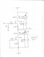
I've posted a schematic below, adapted from one the one discussed on the other site. (Sorry my artwork is so bad... Hope it's legible). Although I couldn't find one with the caps on it, I'm sure I saw it somewhere, and the pcb clearly shows them, so they should be there, I guess, as they are on the DAO with Taylo.
Here are a few questions
1. Earlier in the thread Patrick suggested using a jfet in place of the J511. Have I got them wired up right on the schematic?
2. I have a few 2N5457 on hand, and should have rather more J309 or J310 here somewhere. Any need to use matched pairs in the circuit? If so, I probably don't have enough 2N5457, so how about J309/310, or MPF102, which I know I can get my hands on?
3. Is the function of the capacitors just to eliminate noise from the zeners? I notice that the original version Steenoe built didn't use them, so I guess the circuit should work OK without them. (Right?) I ask because I am using the small boards, and the caps I have (Elna Silmic II) are surprisingly large, which makes it dificult to mount them and still get DMM probes in to measure anything once it's working. I thought I could try things out and only put them on when everything else checks out.
4. (A real newbie question) On the other thread Patrick says to use the central mounting point on the boards as the star earth point. I presume this means an insulated screw holding it to the heatsink, and the three connections shown on the board are for the input, output and voltage grounds... Right?
5. (Another newbie question) Is there any reason I shouldn't put the resistor from input to ground directly on the RCA input socket? I've done it before with other amps, but this time I've gone to the trouble of importing "quality" parts and so on, so I'd like to really try and keep noise and hum down as far as possible.
I'll post photos when finished if anyone is interested.
Cheers
Nigel
I thought I'd post a progress report, and ask a few questions.
I've finished the chassis, (first version of a) power supply, and a protection and muting circuit. The PSU is a CRCRC filtered, unregulated supply, giving about +/-21V DC. A friend helped me measure ripple - at around 65mV peak-to-peak when supplying about 400mA, which is close to normal use in this case. (That's in an Elec. Eng. lab with the top of the supply off, so a really noisy environment. Ripple will probably be a bit better than that in practice.) The PSU is in a separate case from the amp; there is a further "snubberised" 4700uF on each rail inside the amp itself. Protection and muting circuit is the one from the ESP site (project 33).
I'm doing the DAO without Taylor mod. I've decided to do this and live with it while on leave (as mentioned above). I can mod it or build another when I come back if I feel like it. I also decided to go with the first pcb design; this may have been a mistake, in retrospect, but it's too late now...
I've posted a schematic below, adapted from one the one discussed on the other site. (Sorry my artwork is so bad... Hope it's legible). Although I couldn't find one with the caps on it, I'm sure I saw it somewhere, and the pcb clearly shows them, so they should be there, I guess, as they are on the DAO with Taylo.
Here are a few questions
1. Earlier in the thread Patrick suggested using a jfet in place of the J511. Have I got them wired up right on the schematic?
2. I have a few 2N5457 on hand, and should have rather more J309 or J310 here somewhere. Any need to use matched pairs in the circuit? If so, I probably don't have enough 2N5457, so how about J309/310, or MPF102, which I know I can get my hands on?
3. Is the function of the capacitors just to eliminate noise from the zeners? I notice that the original version Steenoe built didn't use them, so I guess the circuit should work OK without them. (Right?) I ask because I am using the small boards, and the caps I have (Elna Silmic II) are surprisingly large, which makes it dificult to mount them and still get DMM probes in to measure anything once it's working. I thought I could try things out and only put them on when everything else checks out.
4. (A real newbie question) On the other thread Patrick says to use the central mounting point on the boards as the star earth point. I presume this means an insulated screw holding it to the heatsink, and the three connections shown on the board are for the input, output and voltage grounds... Right?
5. (Another newbie question) Is there any reason I shouldn't put the resistor from input to ground directly on the RCA input socket? I've done it before with other amps, but this time I've gone to the trouble of importing "quality" parts and so on, so I'd like to really try and keep noise and hum down as far as possible.
I'll post photos when finished if anyone is interested.
Cheers
Nigel
Attachments
Thanks, Patrick.
1. OK
2. I've got 2SK170BL also, I think, so no problem. (I don't know why I didn't think of those...)
3. The schematic for the DAO with Taylor showed 220uF, so that's what I bought. I can change to 22uF easily enough, although they'll be Epcos or something, not Elna. (Probably makes little/no difference...)
No answers to 4 and 5? Too obvious?
Thanks again
Cheers
Nigel
... 2) J309 has too much Idss. Use 2SK170BL. 7mA is more than enough. Needs rough matching (+/- 1mA or so). ...
I don't think that high Idss is an obstacle to use J309. One Source resistor solves that - something between 100R and 220R should be OK.
Hi juma,
Yes, but there's very little space for an extra resistor, so since I have plenty of 2SK170 (I think - I'll have to check...) I can just use those.
What about 4 and 5? Only issue is avoiding ground loops and minimising noise, other than that it's all clear to me.
Cheers
Nigel
I don't think that high Idss is an obstacle to use J309. One Source resistor solves that - something between 100R and 220R should be OK.
Yes, but there's very little space for an extra resistor, so since I have plenty of 2SK170 (I think - I'll have to check...) I can just use those.
What about 4 and 5? Only issue is avoiding ground loops and minimising noise, other than that it's all clear to me.
Cheers
Nigel
Sorry, never noticed this follow up question until today.Hi Andrew. I think I got all that except the last sentence - Do you mean that since these are (usually) short-lived situations you don't have to worry too much about heat generation?
The two worst case conditions are during Fault of some kind. The audio side cannot be working and therefore audio quality is unimportant.
However, both fault conditions could be long term and you would expect the regulator to return to normal temperatures on removal of the fault and perform as well as it did before. You need to check junction (Tj) and case (Tc) temperatures during the worst case conditions.
If you run into ground loops and noise you'll notice......What about 4 and 5? Only issue is avoiding ground loops and minimising noise...
If you run into ground loops and noise you'll notice...
Yeah, I guess so... Since I posted earlier I have been thinking "what the hell, I can always try it and see what happens..."
Cheers
Nigel
How about tantalum caps?
I stopped off after work to get some smaller caps, and ended up buying standard 22uF 50V aluminium electrolytics (Epcos) and also some nice-looking 22uF 35V tantalums. The parts guy there (who knows his stuff but isn't into audio at all) says they are much better quality than the Epcos (and they certainly look a better quality part), but I've never used tantalums before.
A search on the web showed they are often used for bypassing and so forth, which sounds like much the same thing as here. Since I'm going to try the amp without caps first, I could also just try both types to see, but in this case it'll be a real pain in the a** to pull caps in and out of such a small space, so I thought I'd ask here if there is any downside to the tantalums before I put them in.
Anyone have any thoughts?
Cheers
Nigel
Nigel.
Caps - you're just going to have to listen for yourself - it's very subjective and mostly different for everyone.
The Epcos caps that I tried were a bit "slow" and now using a Nichicon KZ on top arm of cct, and a Silmic on the bottom - it just suits my system and musical taste - I didn't like the sound of Tants here, (or Oscons, either) but you'll have to try for yourself.
My k701's now have some fancy multistranded wire on them, so h.amp requirements are a bit different.
There is a slight difference when using the fets (plus resistor) as current sources and if you are doing a perfboard build, suggest try them - quieter sound, slightly.
In fact, with such a simple cct, everything will have an effect to some degree but with the very small pcb layout, not as many options for you.
It does sound quite a bit better when running the power fets hot - somewhere between 55 -> 60*C - lot of top amps run this hot, or more, with good results.
It's much better with really good power supplies and especially revealing of the music source limitations!
Remarkable cct - well worth perservering with it.
Hi James,
What fet and resistor did you use? Following Patrick's remark above I put 2SK170 in, measured and rough-matched at around 7.5mA, no resistor.
I hope to try out different things with PSU and the main circuit, and will try the Taylor mod at some point. However, since I won't have any decent headphones until I'm actually *on* my sabb. leave and buy them, I won't be able to do much tweaking "by ear" until I get back - which is quite a long way off. Which is one of the reasons I'm asking about tantalum caps, and so forth...
Cheers
Nigel
There is a slight difference when using the fets (plus resistor) as current sources and if you are doing a perfboard build, suggest try them - quieter sound, slightly.
In fact, with such a simple cct, everything will have an effect to some degree but with the very small pcb layout, not as many options for you.
What fet and resistor did you use? Following Patrick's remark above I put 2SK170 in, measured and rough-matched at around 7.5mA, no resistor.
It's much better with really good power supplies and especially revealing of the music source limitations!
Remarkable cct - well worth perservering with it.
I hope to try out different things with PSU and the main circuit, and will try the Taylor mod at some point. However, since I won't have any decent headphones until I'm actually *on* my sabb. leave and buy them, I won't be able to do much tweaking "by ear" until I get back - which is quite a long way off. Which is one of the reasons I'm asking about tantalum caps, and so forth...
Cheers
Nigel
how did you carry out this before and after listening test?It does sound quite a bit better when running the power fets hot - somewhere between 55 -> 60*C - lot of top amps run this hot, or more, with good results.
Getting amp cables into the oven and back out to the speaker must be quite awkward when you are listening in the lounge.
or,
maybe you changed the output bias?
Yeah Nigel, can't rush these things!
The k170s were a couple of higher Idss ones that I throttled back to 5ma - nothing fancy - I imagined it was better, one of my better abilities!
Hi Andrew,
... my country childhood (rusted threads = blowtorch!) - I just gave the heatsink a burst of the old heatshrink gun - later on, I blocked off fins on the heatsink and measured the temp rise and called it quits at 75*C as the shunt reg fets are on the same sink and aren't so happy about Lucifer's touch!
About 60*C is the "sweet spot" in my version of Patrick's particular bunch of bits - may not be the same in other circumstances, tho
I did intend to build a balanced version of this cct - maybe someday ....
Do you still have any of those higher current LSK170s in your parts box, and any idea of their TC at 10mA/20volts? - I would like to try them in D1 o/p stage as a replacement for the IRF610s at 10mA.
Hi,
Following Patrick's post earlier, and James reply now, I wonder if the 2SK170s I put in at 7.5mA need "throttling back" to 5mA... This means a small resistor between gate and source, right?
Thoughts? Am I OK at about 7.5mA? And what difference would a higher Idss make anyhow?
Cheers
Nigel
Following Patrick's post earlier, and James reply now, I wonder if the 2SK170s I put in at 7.5mA need "throttling back" to 5mA... This means a small resistor between gate and source, right?
Thoughts? Am I OK at about 7.5mA? And what difference would a higher Idss make anyhow?
Cheers
Nigel
- Home
- Amplifiers
- Pass Labs
- Some other Source Follower Configurations