hi!
news from my preamp...
when I shorten the input, I get +140mV on the output.
turning the pot is giving me +-15mV (from +165 to +140mV)
- the fets are matched (both have 10mA) perfectly.
- negative rail has got -11.88V
- positive rail has got +12.2V
and that's only ONE of TWO failed channels.
I don't know WHY?!
pics will follow!
best regards,
matthias
Check voltage drop across R4 an R5 - it should be equal (when resistor values and current through JFETs are equal). Voltage drop across R6 and R7 should be equal too.
Check your BJTs' hfe - there shouldn't be a big difference between them.
Also check all the connections, orientation of all transistors and resistor values - it's very simple circuit, there's not much that can go wrong...
Check your BJTs' hfe - there shouldn't be a big difference between them.
Also check all the connections, orientation of all transistors and resistor values - it's very simple circuit, there's not much that can go wrong...
Spencer supplies well matched devices and gives good service with tracking number in fact some arrived this morning.Only one week from dispatch to delivered.
i would also like to second/third all the good comments about spencer.
i got 20 or so jfets from him.
i had my fingers crossed, ive read about fakes allover.
not only where they not fake, but well matched!
ive got his fets in my Xono, a preamp for my dad, and im playing with this pre too and a simple jfet riaa from salas in a breadboard rightnow.
Check voltage drop across R4 an R5 - it should be equal (when resistor values and current through JFETs are equal). Voltage drop across R6 and R7 should be equal too.
Check your BJTs' hfe - there shouldn't be a big difference between them.
Also check all the connections, orientation of all transistors and resistor values - it's very simple circuit, there's not much that can go wrong...
hi juma and thank you for the answer!
hmmm, the only thing I can imagine is, that I have a big error in my circuit?
Are there any other mistakes I could have done? I have no 10k-Pot in the Circuit yet, but that should be no problem, I think?
the resistors aren't matched, but have the correct values.
the BC550/560 aren't matched, too.
Have all the parts in the circuit been matched to work properly?
hfe is something I heard about, but don't know how to measure it exactly?
It's such a simple circuit, and I can't find the mistake I made...
I'll build it completely new, and try again.
Sometimes I think I'm a big big idiot...
Electronic is a strange thing... It's big part of my job, but I don't understand 90% of it...
If you have any other hints for me, feel free to write them down here!
Thank you!
Best Regards,
Matthias
Hi everbody!
As a rule of thumb: BC550C has got the same pin configuration as BC560C!
I thought, I have to turn 560C 180 degrees?! Reading a datasheet isn't always a bad idea...
Now I can adjust it to 0mV +/-2mV.
But If I cut the connection to ground on the input, it drifts away (sometimes +560mV, sometimes -560mV, etc...)
Is that because of the open input without any load?
Best regards,
Matthias
Gates of JFETs must have reference to ground (R3).
Standard working mode of the preamp is with input connected to signal source.
Using an input cap is optional (depends on your signal source - if it puts the DC voltage out or not).
Volume pot is needed to regulate the signal level.
Standard working mode of the preamp is with input connected to signal source.
Using an input cap is optional (depends on your signal source - if it puts the DC voltage out or not).
Volume pot is needed to regulate the signal level.
hi juma!
R3 is installed correct. So is it normal, what my preamp is doing?
Open Input brings +560mV to -560mV on the output.
I know that normally a device is connected to the input, but if it isn't, I could get massive DC on my speakers, because of no input cap in my F5.
Best regards,
Matthias
R3 is installed correct. So is it normal, what my preamp is doing?
Open Input brings +560mV to -560mV on the output.
I know that normally a device is connected to the input, but if it isn't, I could get massive DC on my speakers, because of no input cap in my F5.
Best regards,
Matthias
Hello!
Now it works!
I built it completely new.
The only thing is a small hum while running the F5 with preamp.
But I think its because I use loooong wires without shield (those with small clamps on every end) for testing everything.
So I can start to assemble the rest of my preamp!
THANKS TO ALL HELPING HANDS HERE!!!
Best regards,
Matthias
Hello,
Thanks for the tip on 2sj74. I contacted Spencer and ordered the real things.
While the fets are on their way I examined the possibility to get higher voltage swing for my purposes, since my current buffer can push over 100w inro 8ohms.
Here is a prelimiray schematic for pre with higher voltage swing capacity.
Part values are chosen according to what I have in my drawer at the moment.
What do you guys think?
Attachments
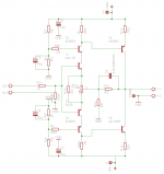
Input stage looks OK, but the output is not up to the task. If you want BJTs at the output some composite stage (Super Pair, Darlington, etc.) would be more appropriate - the way you drew it, a992/c1845 can't take the heat and they will load the input stage a bit too much with the output swing you want (for 100W @ 8 Ohms you need +/-40V swing ie. 28V_RMS). Also, we know nothing about your power buffer's Zin.
If I were you, I'd rather use k2013/j313 as output pair, biased at 50mA or so.
If I were you, I'd rather use k2013/j313 as output pair, biased at 50mA or so.
Hi Juma
Thanks for the info. My current buffer is Steven Dunlaps Krill outputstage. I currently drive it with e88cc anode follower. The input impedance is several hundred kohms so the load is very light.
My initial thought was to use sk2013/sj313 since I have 8 pairs of those in my drawer but using bjt:s at the output is temting for some reason.
I´ll do some research on the subject.
Hi Juma!
I (maybe) have a problem with my preamp.
If I put a square-wave signal with 6Vpp on the input, my negative waveform looks like a saw on the output.
The positive wave looks absolutely perfect, no problems here.
Staying under 6Vpp --> everything is fine.
The "saw" is about 1Vpp big and isn't changing its value while going higher than 6Vpp on the input, is it a "ripple"?
Or something like "clipping"?
If I switch to sinus-waveform, everything is fine...
How much Vpp is needed on the input of this preamp to drive my F5 full?
Thank you- as always- for your answer!
Matthias
GentryBa,
1. Do all the resistors have values as in the schematic from post #53 and if not, what is different (what are the exact values of R8 and R9) ?
2. What is the value of PS voltage ?
3. What's the voltage drop across R4, R5, R6, R7 ?
4. What waveforms are problematic - at preamp's input or output (look at both of them and see if it's the case of garbage-in-garbage-out) ?
5. What's your square wave source, was it properly loaded, what did you use as preamp's load when measuring?
If you made your preamp exactly as shown in the schematic from post #53 you need about 3.5V_peak-to-peak at preamp's input to drive the standard F5 to full power.
Pictures of problematic waveforms at preamp's input and output will help.
Hey Juma!
Thanks for you help, I try to answer:
1. I built it as you posted it. All the resistors have the same values.
2. PS has got 16VDC, regulated by 78/7912 regulators to get 12VDC on the output.
3. Didn't measure, will describe later.
4. Here is the solution:
On the input everything seemed to be ok, but when I put the probe to the output, I could see the saw-ripple.
Then I switched off my pulse-generator (it's an ascel-diy from ebay, calibrated with a nice fluke in my work, very fine for the money!), and noticed a bad ripple on the output without any load on the input/output. (It didn't change when I put a 100K on the output to simulate the F5 a little bit)
(I have to say, my hameg HM512 is veeeery old and not the best at all...)
After some measuring I found out, that a 10µF capacitor between output and input pin on the 7912 helped. No ripple yet, nice and smooth waveform on the output!
I'm wondering why? But ok, now everything is fine, and I continued measuring.
Is it ok to have ca. 7.8Vpp on the output, when I put 3.9Vpp on the input?
I checked with different values, and everytime I got Vpp(in) x 2 = Vpp(out).
More than 7.8Vpp wasn't possible, but I think, this is more than ok to drive the F5?
best regards,
Matthias
Strange... 10uF cap should be between output and ground (also between input and ground), not between input and output. If it's really so, something's wrong with 7912 chip which is also nothing unusual considering the number of faulty chinese chips that are currently circulating in distributors' networks. to be safe, use the exact schematic from post #53 and add two 10uF caps - one parallel to C1 and the other one parallel to C4....10µF capacitor between output and input pin on the 7912 helped.
Yes. Your output stage is probably a bit starved so Zout is a bit higher (for that, you'll have to answer Q. nr. 3. from post #354) and that causes the gain to be a tad lower....Is it ok to have ca. 7.8Vpp on the output, when I put 3.9Vpp on the input?
7.8V_peak-to-peak is exactly what you need to drive the F5 to full power.... More than 7.8Vpp wasn't possible, but I think, this is more than ok to drive the F5? ...

Hi
Do this preamp from Juma could drive lower Z load than the F5 ?
What are the minimum Z load it could drive ?
And where do we connect for the output, across R8 ?
I presume that R7 are the feedback ?
Thanx
Paul
Last edited:
1. Yes, but not with great success - as it is, it has Zout of 1k5
2. I wouldn't go below 47k or so...
3. R8 represents the load
4. No. R7 puts J2's Gate to ground
That circuit can be used as SE to Balanced converter, or just as a SE preamp which has output in phase with input. Pretty basic stuff, but a lot can be built upon it...
2. I wouldn't go below 47k or so...
3. R8 represents the load
4. No. R7 puts J2's Gate to ground
That circuit can be used as SE to Balanced converter, or just as a SE preamp which has output in phase with input. Pretty basic stuff, but a lot can be built upon it...
1. Yes, but not with great success - as it is, it has Zout of 1k5
2. I wouldn't go below 47k or so...
3. R8 represents the load
4. No. R7 puts J2's Gate to ground
That circuit can be used as SE to Balanced converter, or just as a SE preamp which has output in phase with input. Pretty basic stuff, but a lot can be built upon it...
Hi
This circuit was interesting because the guy wrote that it should be better sounding than the B1, but since I only have 2SK170 fets, I may made the B1 with gain that you did design.
Btw, Have you try that B1 with gain circuit, how does it sound ?
Thanx
Paul
Attachments
Last edited:
...Btw, Have you try that B1 with gain circuit, how does it sound ? ...
I'd say great. Have a look here:
http://www.diyaudio.com/forums/pass-labs/146310-bf862-preamp.html
- Status
- This old topic is closed. If you want to reopen this topic, contact a moderator using the "Report Post" button.
- Home
- Amplifiers
- Pass Labs
- Preamp ideas for F5