B1 BUFFER
Hi
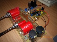
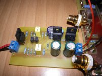
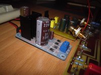
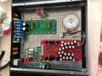
this is my B1 Buffer .
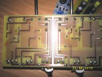
Pcb its from gerber fille .
2sk 170 matched to 7.8 ma at 640 mv gs... Offset is 17mv at start and after few seconds going down to 0 V when i have connect the output to input of my amp .When the output its not connected to input of my amp offset is 400mv end going down to 0v after two or three minutes
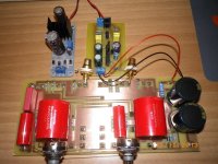
10mf-1mf Audiophiller
JLH Shunt Reg at 24V
LM 317 at 24.10 V from china
Two separate pots 25kΩ
Very detail- low dynamics- each region frequency has her own dynamic .But every frequency has its own dynamic
and this is what makes the buffer special.
Hi
this is my B1 Buffer .
Pcb its from gerber fille .
2sk 170 matched to 7.8 ma at 640 mv gs... Offset is 17mv at start and after few seconds going down to 0 V when i have connect the output to input of my amp .When the output its not connected to input of my amp offset is 400mv end going down to 0v after two or three minutes
10mf-1mf Audiophiller
JLH Shunt Reg at 24V
LM 317 at 24.10 V from china
Two separate pots 25kΩ
Very detail- low dynamics- each region frequency has her own dynamic .But every frequency has its own dynamic
and this is what makes the buffer special.
Attachments
Last edited:
 ,
,Ah ok, thanks! I guess linear is what is in my Marantz PM-17(I use it as my preamp on my Hiraga)
It goes loud real fast! So stepped log is the better choice I guess. That's good because the Glasshouse attenuator is already finished")
Let the build begin!
Thanks again!
Sjoerd
It goes loud real fast! So stepped log is the better choice I guess. That's good because the Glasshouse attenuator is already finished
Let the build begin!
Thanks again!
Sjoerd
I would be surprised that Marantz fit a linear track volume pot.
You often find a linear track pot on the input of PA Power Amplifiers where you know the sensitivity setting from the rotation of the adjuster knob.
10% of rotation requires 10 times more signal.
50% rotation requires 2 times more signal.
You often find a linear track pot on the input of PA Power Amplifiers where you know the sensitivity setting from the rotation of the adjuster knob.
10% of rotation requires 10 times more signal.
50% rotation requires 2 times more signal.
Grounding for B1
Dear friends,
Sorry, if this question was already discussed but I still have not met the answer.
Hope someone will help me.
The B1 board from Mr. Nelson Pass has mounting holes which are connected with GND conductors on the board.
So, it seems, that it was assumed that board GND circuit to be connected to the chassis... At the same time in F5, the signal GNG is separated from EARTH via thermistor.
Please, kindly advice me which way should I follow here - to use insulated mounting pins and use thermistor as in F5 or to use chassis as a signal ground (doubtfull)?
Best regards, Anton
Attachments
B1 progress
Hi,
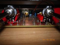
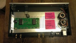
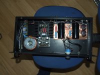
We are getting somewhere!
All power related wires are under the baseplate, witch is grounded....
Still waiting for the extender rods and the new attenuator.... The one in the picture is unfortunately broken so I went for a nice Khozmo stepped one from HiFi Collective..... It should arrive this weekend!
Any tips?
Hi,
We are getting somewhere!
All power related wires are under the baseplate, witch is grounded....
Still waiting for the extender rods and the new attenuator.... The one in the picture is unfortunately broken so I went for a nice Khozmo stepped one from HiFi Collective.....
It should arrive this weekend!Any tips?
Attachments
Pots
Thanks for the website tip Some good stuff there. I'll go for the Khozmo in this project because it was not cheap and it's on the way . It's supposed to be really good! Can't hurt to try it the Rod Elliot way
It's not commonly used but you can get better matching and an almost logarithmic performance using a linear pot paralelled with another resistor.
Rod Elliot wrote an article on the subject on his website.
Thanks for the website tip
Some good stuff there. I'll go for the Khozmo in this project because it was not cheap and it's on the way . It's supposed to be really good! Can't hurt to try it the Rod Elliot wayWires
Thanks for the tip! I'll see to that!
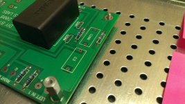
Whaat do you think of the layout so far?
Do any of your wires pass through holes in the baseplate?
If so, then BOTH the Flow AND it's Return MUST pass through the same hole.
Thanks for the tip! I'll see to that!
Whaat do you think of the layout so far?
The PSU requirements of the B1 are not that critical. Nelson himself used a plain Wallmart wall brick.
As long as the input sockets are isolated from the chassis you can connect live and ground for each socket to the B1 board.
Mine is as silent as a graveyard, even with a 100W amp at full volume and your ears pressed against the bass cones.
As long as the input sockets are isolated from the chassis you can connect live and ground for each socket to the B1 board.
Mine is as silent as a graveyard, even with a 100W amp at full volume and your ears pressed against the bass cones.
Attachments
Last edited:
- Home
- Amplifiers
- Pass Labs
- B1 Buffer Preamp