Hi everybody,
as usual, sorry for my english first of all....
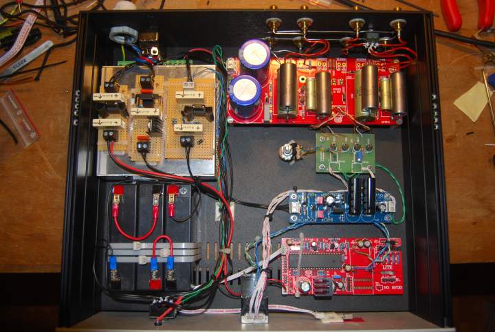
Finally I finished the second B1 buffer....
This time I wanted a remote controlled unit, so I decided to use a cheap ebay pcb with remote to control a motorized pot on the Lightspeed attenuator kit by Uriah Dailey....
These cheap remote pcb's are not so good for working on signal but using it only for controlling the 5v supply to the LDR's I don't risk any kind of noise, I hope....
This time I used k73 caps bypassed by teflon k40, only precision resistors on board and 0,01% res on signal...
This time I use three 6v sla batteries for 18v B1 psu and a simple charging/mantaining circuit for charging them....
If I understood well, the 5v supply to the LDR's has to be the "cleanest" possible, so I used a JLH Ripple Eater after a simple 7805 regulator....
With a 24v switching PSU and a simple quadripolar switch, with one movement, I can select between powering the charging/mantaining circuit or giving power to the 5v to LDR's, 18v to remote pcb and connecting batteries to B1...
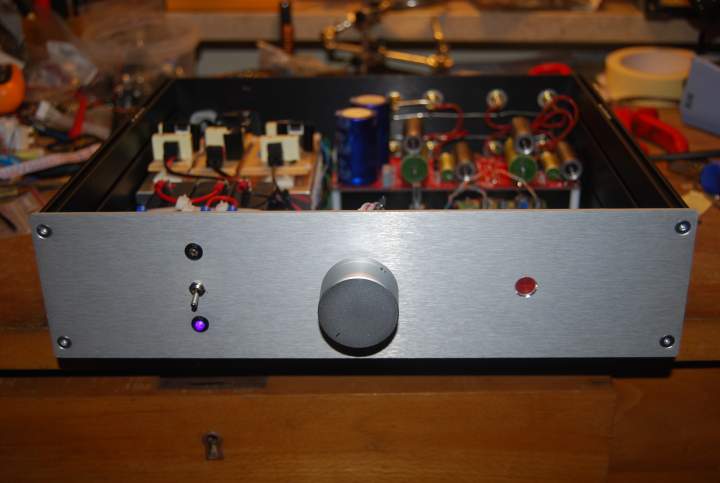
The sound of battery powered B1 with Lightspeed is IMHO very very good and I'm really happy I finally can sit on sofa controlling volume with the remote!
I'm really becoming the italian version of Homer Simpson!
Thank you, Nelson, for this little diamond you shared with us!
as usual, sorry for my english first of all....
Finally I finished the second B1 buffer....
This time I wanted a remote controlled unit, so I decided to use a cheap ebay pcb with remote to control a motorized pot on the Lightspeed attenuator kit by Uriah Dailey....
These cheap remote pcb's are not so good for working on signal but using it only for controlling the 5v supply to the LDR's I don't risk any kind of noise, I hope....
This time I used k73 caps bypassed by teflon k40, only precision resistors on board and 0,01% res on signal...
This time I use three 6v sla batteries for 18v B1 psu and a simple charging/mantaining circuit for charging them....
If I understood well, the 5v supply to the LDR's has to be the "cleanest" possible, so I used a JLH Ripple Eater after a simple 7805 regulator....
With a 24v switching PSU and a simple quadripolar switch, with one movement, I can select between powering the charging/mantaining circuit or giving power to the 5v to LDR's, 18v to remote pcb and connecting batteries to B1...
The sound of battery powered B1 with Lightspeed is IMHO very very good and I'm really happy I finally can sit on sofa controlling volume with the remote!
I'm really becoming the italian version of Homer Simpson!
Thank you, Nelson, for this little diamond you shared with us!
Battery PS
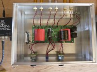
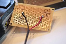
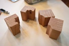
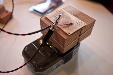
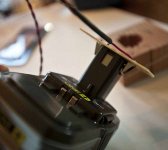
Greetings, Just finished the B1 a week ago. This thread helped answer questions. I had an interesting idea for a battery PS. Hooked it up today to test. Used battery from Ryobi power drill. Measures 19.2 volt, Lithium rechargeable and I have the charger. Here are some photos of B1 and how I am connecting the battery.
Made the wood form using routed 2x4 to hold the battery clips. This will prevent polarity accidents. I will cap the unit with some oak to finish. Battery good for about 60 hours. Large battery will give 120 hours and has power gauge. If you have battery, other parts are inexpensive. You could add a switch, but it is easy to disconnect. And yes it sounds better with battery IMHO. Thanks to Nelson for a great design.
-Howie
Attachments


Howie - That's really neat! I love the idea of using the drill battery! The plug/adaptor you made is a neat solution to powering the buffer.
budwiser - Looking very nice! Is the Energizer module a battery? What rating? You might be able to run it from that for a long, long time.
budwiser - Looking very nice! Is the Energizer module a battery? What rating? You might be able to run it from that for a long, long time.
Last edited:
help for B1
Hello good people,
I just finished building my B1. Unfortunately stopped reading this loooong thread at page 101.
It would be great if someone could be kind enough to confirm what I am doing is right.
My discreet dac outputs 25 ohms, then comes the B1, as a pot I use R2R boards with remote control capacity. i believe the impedance is 10k.
Préamplification - Contrôleur de volume stéréo à commutation de résistances
I was planning to plug this power supply which I already have. It is regulated, +/-18v, is there any way to use both outputs? If not how can I short the -18v, or shall I just leave it unconnected?
ºÍ§Óµ响
I have changed the 1k output resistors to 348 ohm I guess it will not hurt.
One last question: I don't need two inputs so how can I do not to use a switch and just plug in the rca from the dac?
The B1 then get connected to the Linkwitz Orion crossover boards, 10k input impedance.
Any help would be very much appreciated! Thanks in advance.
Laurent
Greetings Laurent!
Regarding the switching -- Are you using the Pass DIY circuit board?
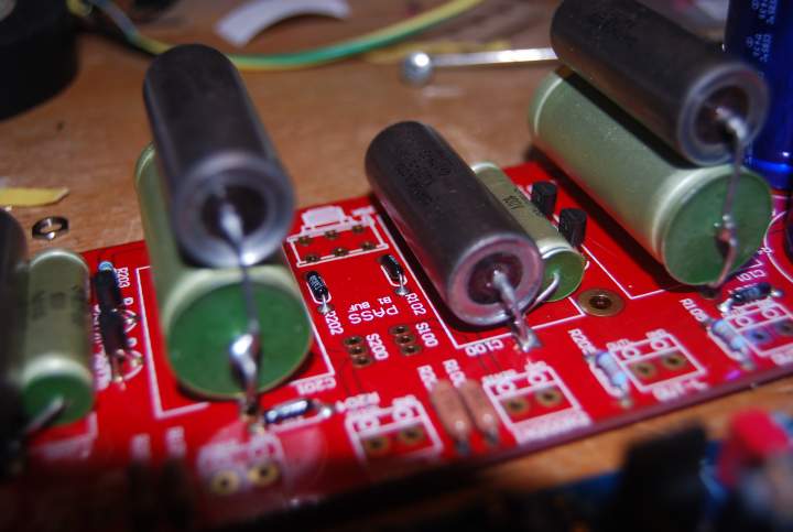
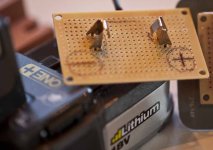
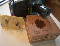
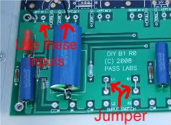
If yes, to use only one input, connect a jumper from the center of the switch pads to "R1" and "L1", and then use only the "1" input pads on the edge.
You can see the jumper in the center of this photo, and the input pads.
Regarding the switching -- Are you using the Pass DIY circuit board?
If yes, to use only one input, connect a jumper from the center of the switch pads to "R1" and "L1", and then use only the "1" input pads on the edge.
You can see the jumper in the center of this photo, and the input pads.
I believe you can use just one side (V+) of your board. It should be no problem.
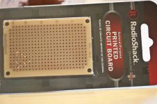
If you would like to save your +18 -18v board for another project, you could build a simple PSU circuit from a LM317 regulator and some perfboard. I used the circuit directly from the datasheet and it works beautifully.
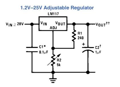
Of course, you would want to add some bigger caps in parallel with the two caps already shown.
If you would like to save your +18 -18v board for another project, you could build a simple PSU circuit from a LM317 regulator and some perfboard. I used the circuit directly from the datasheet and it works beautifully.
Of course, you would want to add some bigger caps in parallel with the two caps already shown.
Power caps for B1 ?
Hey guys would these power caps work for B1
capacitor_film_asc.html
would I need the AC or DC unit and I assume 15uf.
or is there a better choice,I currently use the Panasonic 15,000 uf
Hey guys would these power caps work for B1
capacitor_film_asc.html
would I need the AC or DC unit and I assume 15uf.
or is there a better choice,I currently use the Panasonic 15,000 uf
I use Nichicon KG caps. Perhaps Nelson or someone with a better technical background than mine can comment as to the suitability of a cap that is a 1,000 times smaller in that position in that circuit.
Those caps typically find themselves in vacuum tube high voltage supplies, not low voltage low current supplies.
Best,
Those caps typically find themselves in vacuum tube high voltage supplies, not low voltage low current supplies.
Best,
Would you say the Nichicon KG sound better than Panasonic.
I use Nichicon KG caps. Perhaps Nelson or someone with a better technical background than mine can comment as to the suitability of a cap that is a 1,000 times smaller in that position in that circuit.
Those caps typically find themselves in vacuum tube high voltage supplies, not low voltage low current supplies.
Best,
- Home
- Amplifiers
- Pass Labs
- B1 Buffer Preamp