What your are describing ins the DCB-1. This is already a published design in the forum, boards were group buy made. I have built one of them.Hi,
I've been thinking about the B1 (actually build one as well) and it's power supply.
As I see it, the concept is: take a descent DC-supply. Then follow that by a RC-filter (R1, C1, C2, C3 in the original schematic) to have a really nice supply.
Of course the PS impedance gets larger (R1 is doing that) but that is apparently not a problem because (now follows my thinking)
1. the B1 draws only a little and fairly constant current?
2. there is enough capacity after R1 to provide the current needed (see 1.)?
If this reasoning holds, then increasing R1 gives us a lower corner frequency (less HF-noise), without penalties (the increased PS impedance is not a problem, see 1 and 2).
Please enlighten me, does this reasoning hold, or am I missing something important?
The reason I ask (of course I'd like to understand) is that if this holds, it's very easy to make a symmetrical B1 which is much more in line with the original asymetric circuit by Pass than the interesting circuits proposed by Salas (as mentioned in e.g.: http://www.diyaudio.com/forums/pass-labs/145201-building-symmetrical-psu-b1-buffer.html).
It goes like this:
Start with the (first?) symmetrical schematic by Salas http://www.diyaudio.com/forums/attachments/pass-labs/134693d1243979226-building-symmetrical-psu-b1-buffer-b1psu2xsmall.jpg. Leave out the LM317/LM337 stuff.
Take a decent symmetrical DC-supply. Follow that by an RC-filter, where the R is a preset, and feed the circuit by Salas with it. The DC-offset can then by nulled by virtue of the presets.
See pic:
View attachment 209231
Please comment on this setup. Is its smart? Is it stupid? Are regulators (LM3x7) better?
Thank you, MArco
Look down the forum.
Regards,
Regi
What your are describing ins the DCB-1. This is already a published design in the forum, boards were group buy made. I have built one of them.
Look down the forum.
I've read quite a bit about the DCB-1, simplistic Salas low shunt regs and the like. But all I could find was stuff about about running a B1 on some very fancy and complicated regulators with which I guess very low output impedance. That is not what I'm thinking of.
In these threads I couldn't find anything about running it from some simple supply and then an RC filter with adjustable R (so a high impedance supply) so that DC offset can be nulled. Please point me to a relevant post, all these threads are really long and I've read hundreds of posts in them already.
Thank you, MArco
Hi,
you don't need the offset trimming.
Build the +-9Vdc to +-10Vdc dual polarity supply using your standard transformer rectifier and rCRC smoothing.
The jFET follower determines the output offset.
When Vgs is zero at the input then output offset is also zero.
If the current through the follower is slightly low then the Vgs is a tiny -ve voltage. That becomes the output offset.
A big error in setting the follower current results in a bigger output offset.
As the error approaches zero uA the output offset approaches 0.0mV
This setting of the follower current is done with the CCS jFET. That is why it is important to select 2 devices with similar or identical Idss.
It will also be better if these two devices are thermally coupled. So that the Idss in one tracks the Idss in the other with changes in operational temperature.
Dear Andrew,
Thank you! Now lets see if I understand.
I understand that if Q100 (follower) and Q101 (CSS) have perfectly matched idss then I will have zero offset. If they are not matched I will have offset.
If I have dual supply rails which are not exactly equal but of opposite values it doesn't really matter because offset is determined by idss and not by the supply rails. Is that really true?
MArco
Yes, a DCB1 with +10V-5V would work and output offset would be almost zero.If I have dual supply rails which are not exactly equal but of opposite values it doesn't really matter because offset is determined by idss and not by the supply rails. Is that really true?
The reason for it not being exactly zero is that the CCS jFET is not a perfect CCS. As the -10V drops to -5V the CCS current drops from Idss to ~97% of Idss.
The input offset (Vgs) of the follower jFET is now not zero but very slightly -ve due to the top jFET passing ~97% of it's Idss. That input offset becomes the output offset.
You could correct this by choosing a slightly higher Idss for the CCS to bring the output offset back to zero.
But this would leave you with two slightly different Idss jFETs each with different Vds producing different Tj. The offset would vary with ambient temperature.
For improved temperature stability, keep the Idss the same and the supply rails the same.
hey, I'm a bit confused about C2 supply cap
is it applying bias, much like its done with tube amps
http://www.firstwatt.com/pdf/prod_b1_man.pdf
is it applying bias, much like its done with tube amps
http://www.firstwatt.com/pdf/prod_b1_man.pdf
sounds like a 'phase splitter' ?
manual says the LED is for showing power on/off
but per your descibtion, it should stay, and not be removed from curcuit ?
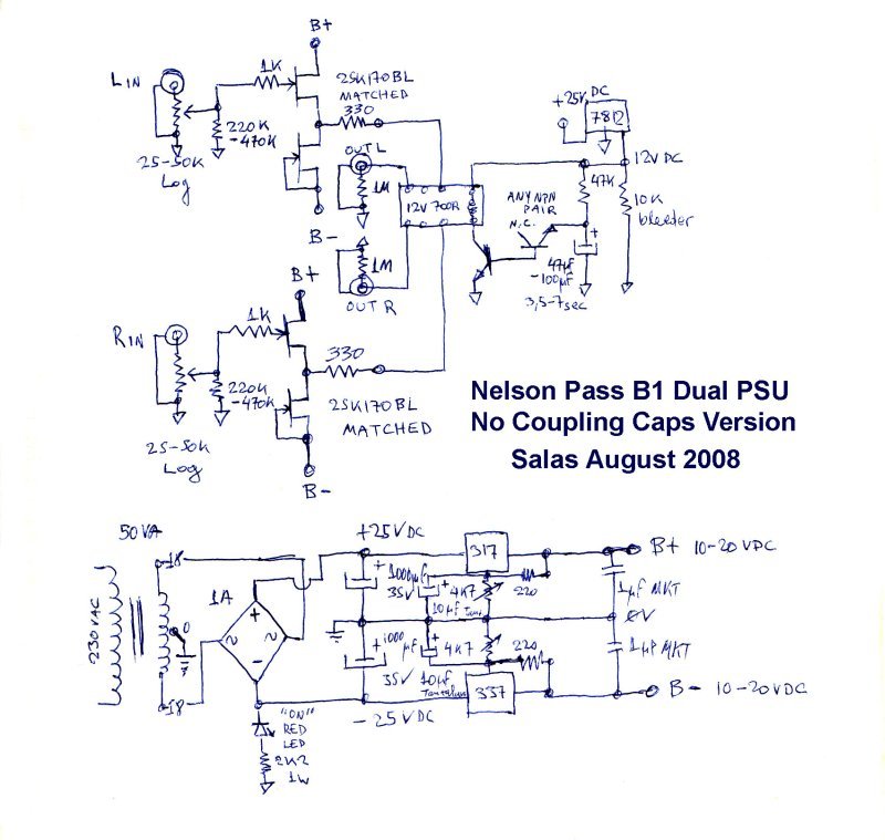
No, like heater lifters and their filter caps. 0-9-18V are created, 9V is centering the buffers by the 1M resistors. Without signal coupling caps it would show 9V at inputs and outputs.
Something's got to drain C1 too also I guess. Double duty. D1 does it for C2. Has no output delay relay, so it would thump at ''on'' I believe if stayed charged.
No, like heater lifters .
ah, yes, like creating a CT point for tube heaters
but why it goes to the signal
centering the buffer input you say
so its got to do with DC balancing, no?
funney, theres a film cap on C2 only, not on C1
http://www.firstwatt.com/pdf/prod_b1_man.pdf
since it is biasing at the gates.
ahh, the 'magic' word, biasing
thanks
in light of this, I think I will use a smaller high quality cap for this special task
and smooth the main supply with a bank of multiple small quality caps, before this 'voltage devider'
and maybe even consider chokes, but not sure about that
sounds like chokes can be sensitive to cap configuration
maybe better to use 'electronic choke'
well, CRCRC, why not, probably fine here
with 15V trafo, should be easy to adjust
Attn: Pass Buffered Preamp builders
Hello,
I'd like to ask some questions of a few of you fellows who have actually built this (using Nelson's boards). Here are some questions to start off:
1) Is there a parts list (with suppliers) posted anywhere?
2) As I understand it, I only need a single board? Is this board for audio only or does it cover the power supply also?
3) What about a easy to understand schematic for using a toroid rather than a so-called "wall wart" power supply?
4) Or, would a "wall wart" power supply be just fine?
5) Does anyone have an online source for the PEC volume pots?
I realize I'll need "extras" such as an enclosure, RCA jacks, a selector switch and the volume pot. Anything else I might consider ordering? I though of standoffs for the board.
Maybe more questions down the line too. I'd like to build one. Just so you know I am an amature, although I have build several Bottlehead kits with success.
Thanks in advance for you help! I'm sure some of my answers appear in this very lengthy thread, which I will attempt to read in its entirety.
My e-mail is ms_williams@hotmail.com if you need it.
Mark
1) Maybe, but just work from the schematic. Parts lists, also called BOM (bill of materials) can be a great way to make mistakes.
2) The Pass DIY board is just the audio and the final PSU filtering/bias. You need a PSU of some sort, something that will supply 18-24volts DC. The current requirements are very small, just about anything will work. You can even run it from two 9v batteries if you want!
3) Look at my thread on the B1 - post #4 covers the PSU http://www.diyaudio.com/forums/pass-labs/181552-b1-preamp-build-thread.html
4) Most likely. That said, building a fancy supply is more fun...
5) I don't. Someone else will
For what it's worth, building a couple of Bottlehead kits is a very good foundation for a project like this! You should have no real problems, as this is simple and basically foolproof. The things that get first-timers in trouble is not the circuit, but all the little stuff, mainly chassis related, that you don't realize you need. Don't worry! Ask as many questions as you need. That's what the forum/community is for... We are all willing to help you get your project to completion!
Last edited:
If you are using the Pass board, read the manual for the B1.
http://www.passdiy.com/pdf/B1 Buffer Preamp.pdf
It lists recommended parts from digikey and mouser. The PEC pots can be found there also. I can look up the part number later if you need it, but i think mouser had them
http://www.passdiy.com/pdf/B1 Buffer Preamp.pdf
It lists recommended parts from digikey and mouser. The PEC pots can be found there also. I can look up the part number later if you need it, but i think mouser had them
- Home
- Amplifiers
- Pass Labs
- B1 Buffer Preamp