If its silent with the inputs shorted, wouldnt that indicate something upstream,i.e. whatever is serving as pre? (or source?)
russellc
That's what I was thinking.
I would try disconnecting the pre-amp signal earths from the pre-amp chassis earth, so that they earth down the RCAs to the power amp and into the star ground there.
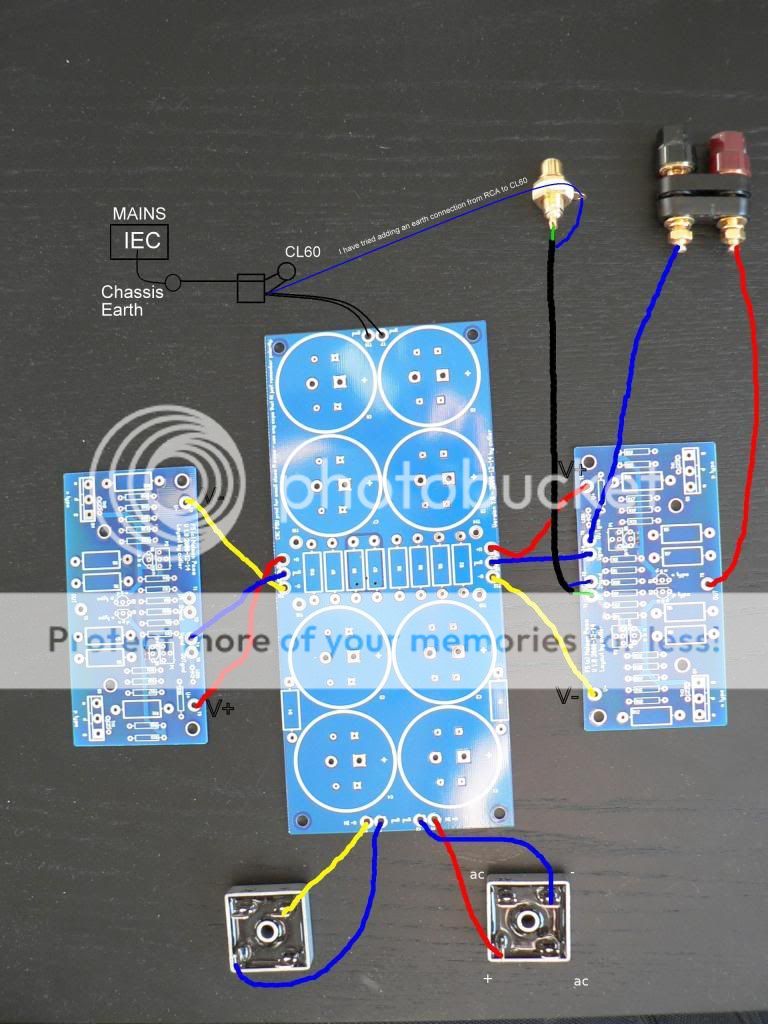
Have you tried removing the thin cable from the RCA to the CL60 altogether. It shouldn't be necessary as if the RCA earth goes to the board, it makes a kind of small cable signal sub star, which is good.
In fact, I think it's a no-brainer. It shouldn't be there.
Also, think of your PS board as the star. It's logical, especially as it has a large ground plane.
In fact, I think it's a no-brainer. It shouldn't be there.
Also, think of your PS board as the star. It's logical, especially as it has a large ground plane.
Last edited:
I would try disconnecting the pre-amp signal earths from the pre-amp chassis earth
absolutely, it looks like a ground loop
RCA jack input is isolated from chassis, and should only connect to amp board
Speaker "negative" should connect to power supply CT point, either directly, or on amp board
Chassis ground should be isolated from Power supply CT by resistor, or the way Nelson does it, via thermistor CL60
This article explains why you might want to degenerate the 2SJ74 to make it truly complementary with the 2SK170.
Patrick
.
EUVL,
What's the impact on amp performance? Have you had a chance to listen or do any measurements?
You have PM.
Last edited:
Thanks for your PM.
I have never used the circuit without this "correction".
But at least on simulation, you do get lower (even order) distortion.
It is easy enough to try out, and is also easily reversible.
Patrick
PS I am not aware that there are other suppliers for 2SK170 & 2SJ74 other than Toshiba.
I have never used the circuit without this "correction".
But at least on simulation, you do get lower (even order) distortion.
It is easy enough to try out, and is also easily reversible.
Patrick
PS I am not aware that there are other suppliers for 2SK170 & 2SJ74 other than Toshiba.
You don't need to do a thing... Patrick is talking about optimizing the input pair to track perfectly or nearly so by using some degeneration and being able to select the devices from a large batch based upon rather precise Idss - something most people can not do for several reasons (no curve tracer, no batch of devices...). Just build it, the amp sounds great (although the sound can vary all over the map depending on the parts and bias used), and some people prefer the slight increase in some harmonics that happens when the devices are not perfectly matched!
_-_-bear
_-_-bear
Someone sent me a PM and asked for clarification regarding manuafacturer of 2SK170 / 2SJ74.
In post #8700, Russellc wrote "Is this the case with all 2SJ74 and 2SK170, or just the Toshibas? ...."
My reply in post#8707 was " PS I am not aware that there are other suppliers for 2SK170 & 2SJ74 other than Toshiba."
I meant there is no other manufacturer for these JFETs, except Toshiba.
A bit of twisted English that might be difficult for non-native speakers.
So my apologies.
I am aware that you can get LSK170 which is supposed to be equivalent.
I have yet to see a LSJ74 even though it has been constantly promised for the last 5 years or so.
Patrick
Ps for those of you who is interested in Nelson's comments :
http://www.diyaudio.com/forums/anal...rch-preamplifier-part-ii-117.html#post2278053
.
Last edited:
As to whether you want to try this or not, I leave it up to you.
Different people chase after perfection to different extremes.
I made the data available for all. So everyone can decide for himself.
You don't need a large batch of both FETs to try these. Stick to the j74 you have, and get some K170s.
There are multiple vendors here selling them at almost dumping prices.
You can even select your own matched pairs from an excel sheet of measured Idss with one guy.
Cost you 6 USD only.
Six dollars to give yourself a chance to decide whether you want even less even harmonics is for me a very tempting experiment.
Patrick
Last edited:
You can even select your own matched pairs from an excel sheet of measured Idss with one guy.
Cost you 6 USD only.
Six dollars to give yourself a change to decide whether you want even less even harmonics is for me a very tempting experiment.
Patrick
Hey I think that's me Patrick! So thanks a lot for the ad. Btw, it's ok to quote my forum name
")
stevejones recently got a set as you specified but I don't have any more of the 0.8mA matched pairs. I hate to break up the closely matched ones though.
absolutely, it looks like a ground loop
RCA jack input is isolated from chassis, and should only connect to amp board
Speaker "negative" should connect to power supply CT point, either directly, or on amp board
Chassis ground should be isolated from Power supply CT by resistor, or the way Nelson does it, via thermistor CL60
Hi Tinitus
The thin blue wire from RCA ground to CL60 is a recent addition. It has been removed, earth is taken from amp board. The speaker negative is also taken from the amp board, as per cvillers diagram. Chassis ground is isolated via CL60.
I'll post the layout of the pre tonight and I will also try adding an input cap in the F5
Last edited:
hey Trip, you are not having trafo mounted close to input/output ?
No, Tripmaster's traffo is at the front, at the other end from ins & outs, like FirstWatt F5.
Just found this. Well worth at least scanning over for top grounding advice. I think I will XLR my next pre and power amps together with some metal braiding as it suggests:
Grounding and Shielding Audio Devices
Grounding and Shielding Audio Devices
Just found this. Well worth at least scanning over for top grounding advice. I think I will XLR my next pre and power amps together with some metal braiding as it suggests:
Grounding and Shielding Audio Devices
Or you can use 2x RCA
and old style cheap standard stereo interconnects
they have seperate shield to each "channel"
as a matter of fact, it would work with almost any kind of stereo interconnects
twice of anything, thats all
I like the small pins on XLR, but sometimes XLR can be too woply and loose to my liking
An externally hosted image should be here but it was not working when we last tested it.
Hi, may i know which one to be exact?
- Home
- Amplifiers
- Pass Labs
- F5 power amplifier