+- 22V DC is quite all right. I used 78L18 and 79L18 on PCB to regulate PS voltage to +-18 V from +-24 (standard F5 PS voltage), but 78L15 and 79L15 will do the job perfectly. You just have to make sure that input PS voltage must be at least 3 V higher than voltage you get from on-board regulators.
F5 Critics anyone??
Allright, I have built and tested F5 for some 3 weeks now. Everything is in spec, fets are well matched, harmonics as they should, THD the same and DC offset less than 1 mV. Initial sound testing was done without thermistors and current limiting transistors and the outcome was very promising. On day 4, I added thermistors (EPCOS NTC 4k7 3%) and limiters and reajusted the bias. I took measurements and everything was spot on again. I used the amp for about 2 weeks driving my horn loaded Tannoy 385s but to my astonishment the bass was a lot less satisfying than before and the mid-highs were congested with no lifelike presentation, overall a very typical transistor mediocre sound. After two dissapointing weeks, I took off the thermistors again and readjusted the amps. The sound improved considerably! the difference is huge, the sound is alot more live, with excellent bass control, life like mid and vocals and excellent resolution and crystal clear extension in highs.
I really cannot explain this really huge difference with the thermistors in the circuit which is not measurable at all, but it is very much there in auditioning the amp. What is worth mentioning is that a friend of mine built exactly the same amps(using the same PCBs and components) and his findings are exactly the same!
Any ideas-explanations are more than welcomed!
Panos,
very interesting findings! The only explanation I could think of, assuming that the thermistors are really the root cause (that is, nothing has been overlooked during experimentation) is that the specific EPCOS models you used are highly nonlinear, changing resistance with voltage and probably additionally having some memory (dynamic non-linear behaviour). One way to test this would be to build a simple resistor divider, 4k7-metallfilm + the 4k7-thermistor and then run distortion tests with that, applying about the same DC bias and the same AC voltage that we have in the circuit (~4V-DC and ~1V-AC or so). If this behaves well, as well as or only slightly worse than a divider with two 4k7 metall-film resistors used for comparison, then it must be witchcraft

- Klaus
very interesting findings! The only explanation I could think of, assuming that the thermistors are really the root cause (that is, nothing has been overlooked during experimentation) is that the specific EPCOS models you used are highly nonlinear, changing resistance with voltage and probably additionally having some memory (dynamic non-linear behaviour). One way to test this would be to build a simple resistor divider, 4k7-metallfilm + the 4k7-thermistor and then run distortion tests with that, applying about the same DC bias and the same AC voltage that we have in the circuit (~4V-DC and ~1V-AC or so). If this behaves well, as well as or only slightly worse than a divider with two 4k7 metall-film resistors used for comparison, then it must be witchcraft
- Klaus
Thermistor behavior is exponential.
Still, I have used both EPCOS and CanTherm and I can't say I hear a difference with either of them, although the measured THD% is lower with the thermistor and current limit resistors.
One more edit -- the thermistor should be as close as possible to the transistor it is measuring.
Still, I have used both EPCOS and CanTherm and I can't say I hear a difference with either of them, although the measured THD% is lower with the thermistor and current limit resistors.
One more edit -- the thermistor should be as close as possible to the transistor it is measuring.
Indeed the THD is slightly lower with the thermistors in circuit. The thermistors are attached to the plastic side of the body of the output mosfets and track the temperature very well. Still the sound is by far superior without these. The difference in sound quality is huge and its not a matter of subjective taste or anything.
At the risk of opening a can of worms......
It is entirely possible that without the thermistors, the distortion specs. are better, and that it sounds worse to a lot of people.
I have made some blind tests with a number of audio nuts, and many preferred some odd harmonic distortion over the possible minimum, the same goes for that people seem to prefer odd over even harmonic distortion.
So, what I'm saying here, is that you just might prefer a little distortion, as it often makes the sound more forgiving and somewhat warmer.
Magura
I completely agree with you Magura, BUT in my case first of all at these extremely low levels of distortion I am really sure I cannot at all detect the harmonic content if it is dominated by 2nd or 3rd harmonic and secondly at least with my speakers I really never use more that 5-10 watts at most, so at these levels harmonic content is even lower and érelevant. Moreover I am not speaking for small difference here, the difference in sound quality is really huge, with the thermistors in the amp becomes a cheap over the counter type of amplifier, while with the thermistors out it is transformed in a real performer in every aspect of audio reproduction.
panos29 said:I completely agree with you Magura, BUT in my case first of all at these extremely low levels of distortion I am really sure I cannot at all detect the harmonic content if it is dominated by 2nd or 3rd harmonic
You just did
Magura
Originally posted by Nelson Pass audiophiles are blessed with incredible hearing or conversely: high-enders are delusional.
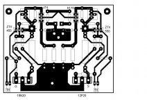
PCB
The high current Source resistors are close and parallel to the TH tracks. It is better to put these R11,12 with supply wires near output mosfets, away from input components.
The rule is: same route for supply currents entering the mosfets - same route them to the speakers.
The high current Source resistors are close and parallel to the TH tracks. It is better to put these R11,12 with supply wires near output mosfets, away from input components.
The rule is: same route for supply currents entering the mosfets - same route them to the speakers.
The second victim of the "thermistor" virus.
I was the first to complain to Panos29 (him been more experienced in SS stuff) regarding the performance of the amp after installing them..
I'm writing just to point out that the difference with and without them is huge.
Luckily the first time I've heard the amp was without them. It was love on first notes..
PS: I'm using the same PCB as Panos29.
PS2: I'm not in the HiEnd arena.
thermistor
Maybe there is something not so great with the layout somehow?
Maybe posting resistor type, wattage, position etc may be insightful. It looks like your source resistors are pretty large. Most would think part types make not so much difference, but maybe the layout here is making the resistance value there in need of some 'dialing in'.
morfeas said:The second victim of the "thermistor" virus.
I was the first to complain to Panos29 (him been more experienced in SS stuff) regarding the performance of the amp after installing them..
I'm writing just to point out that the difference with and without them is huge.
Luckily the first time I've heard the amp was without them. It was love on first notes..
PS: I'm using the same PCB as Panos29.
PS2: I'm not in the HiEnd arena.
Maybe there is something not so great with the layout somehow?
Maybe posting resistor type, wattage, position etc may be insightful. It looks like your source resistors are pretty large. Most would think part types make not so much difference, but maybe the layout here is making the resistance value there in need of some 'dialing in'.


Choky's joking
Nelson already commented on thermistors a couple of times, even in this thread:
Have fun, Hannes
Nelson already commented on thermistors a couple of times, even in this thread:
1) You don't have to use the thermal compensation, particularly
if you have generous heat sinking, but apart from having extra
parts, there is no downside to it. The compensation is fairly subtle
and the open loop variation is insignificant, probably less than
without compensation.
Have fun, Hannes
- Home
- Amplifiers
- Pass Labs
- F5 power amplifier