wrist strap wouldn't be a bad idea; usually just grounding yourself before handling semis is sufficient.
I looked at a couple on the web, looks like cheap insurance for this time of the year here.
Thanks, much appreciated,
Russellc
Oh, New England can be very dry in the winter. I humidify my expensive guitars til at least May.
Hey, I'm just an amateur, I usually rub my feet across the floor before I grab them, bias the hell out of them, then blow them up wrist straps all the way baby!!!
wrist straps all the way baby!!!Is there any method to know that i already overdrive the F5 more than 20watts? because i scare that i kill the amp when i crank up the volume too much
Put all neg RCA and neg binding post to 'center' of dual rail supply. Then connect the CL60 from that point to chassis ground and Power Earth ground.
Do not put the input shielding to star ground but to the board only.
Just in case.
Thanks for your instructions, I did what you said, everthing to the center of dual rail supply and the input only to the board!
Dead quite, using B1 buffer, its the first time i turn the pot to maximun with out any noise!
By the way the highs are here and they are fantastic... it was a ground problem!!!
Pictures coming!
What a balanced and clean sound! Thanks Mr Pass
Testing into a dummy load, use an oscilloscope to compare the input signal to the output signal.any method to know that i already overdrive the F5
Playing music into speakers, use your ears/brain to tell you it's getting too loud.
Is there any method to know that i already overdrive the F5 more than 20watts? because i scare that i kill the amp when i crank up the volume too much
If you massively clip the amp, it is more likely that you will kill the tweeters than the amp...
Not much to worry about. To my ears the amp starts to sound slightly "compressed" when peaks push it into clipping... not much else seems to happen.
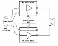
If you need more power, try making a bridged pair per channel??
There are several schemes that have already been posted about this... also the cascode trick too.
_-_-bear
Andrew, have you found the time to build one yet?

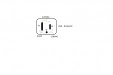
How do I wire the IEC, fuse, and switch?
Its practical to connect one wire to switch, and the other to fuse
Each are in series with wire
Then both wires have a fixed connection
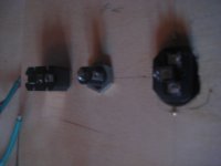
But your mounting of F5 board looks wrong, at one end
It also looks like you risk a short to heatsink
Where does that heatsink come from ?
How do I risk the short to heatsink? I have extra insulators if they are required.
That heatsink is from Papa...
That heatsink is from Papa...
How do I risk the short to heatsink? I have extra insulators if they are required.
That heatsink is from Papa...
Maybe you can keep the insulators oriented with the outputs so the metal underside of the transistor can't touch the heatsink by accident. And maybe move the amplifier board closer to the center of the heatsink.
Last edited:
what tinitus said...
you can peel the heatpads and turn them so that they are square below the Mosfets...
The mosfets get very hot, they should be most of the way down that heatsink, lower is better.
The diodes don't get so hot... you can move them so they are in a square pattern, not a long pattern as they now are...
face their leads at each other too...
That will let you have shorter wires. Shorter is usually good.
_-_-
Last edited:
one insulator per fet, if you need more than one, get the proper insulators (if i'm reading you right). Double check with continuity test from drain to chassis.How do I risk the short to heatsink? I have extra insulators if they are required.
Nothing is wired up yet. The holes were already tapped in the sink and that was the only way I could get the fets to line up with the holes. I will turn the pads...
Regarding my initial question "How do I wire the IEC, fuse, and switch?"...
Positive from the IEC -> one terminal on the fuse. The next terminal on the fuse is wired to one terminal on the switch and the next terminal on the switch to the hot lead on the primaries of the power transformer.
Thanks Gentleman,
Positive from the IEC -> one terminal on the fuse. The next terminal on the fuse is wired to one terminal on the switch and the next terminal on the switch to the hot lead on the primaries of the power transformer.
Correct! With the exception that it's AC, there's no positive as in DC. Make sure L1 connects to fuse>>switch. AC ground>>directly to chassis. Speaker and signal (line level) connects to PS ground or to a star ground. PS/star ground connects to chassis ground via thermistor or bridge rectifier. Take a look at the ZenV4 article, specifically Figure 6 - unregulated power supply example.
-john
Attachments
Last edited:
Curse you DIY AUDIO!!! (kidding...sort of...)
Well, before I had my aleph mini complete I had ordered Peter D's F5 boards and universal PSU...For some reason I can not stop building amplifiers!!!
The aleph mini is a great little amp but I am looking forwards to a little more power. I am currently driving a pair of Fostex FE127E's in the planet 10 Fonken cabinet.
So far I have collected all of the resistors and caps for the amp boards and PSU. Still need misc enclosure bits - rca's speaker terminals etc. and a transformer.
I am not sure If I go with an 18V 20V or 22V unit. Most likely to be a 400VA unit from Antek. I am using a 12V 200VA unit for the mini and am only getting 14V +/-.
And the Pièce de résistance - A hifi2000 4U with heatsinks
High power F5X
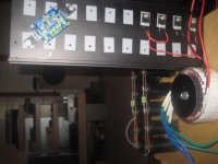
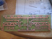
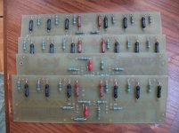
Today I started to populate my high power F5X PC boards .
I need to ad the 3 pair (Toshiba) MOSFETs /PC board and JFets .
Also I will have to buy some 5K trim pot .
I hope soon I can set up for testing .🙂
Some pictures
Greets
Today I started to populate my high power F5X PC boards .
I need to ad the 3 pair (Toshiba) MOSFETs /PC board and JFets .
Also I will have to buy some 5K trim pot .
I hope soon I can set up for testing .🙂
Some pictures
Greets
Attachments
It was already successful built by 3pair IRFP MOSFETs as SE type.
I'll use Toshiba MOSFETs , easier to drive !
In case If I'm unable to set up the X I will connect in bridge mode .
Greets
I'll use Toshiba MOSFETs , easier to drive !
In case If I'm unable to set up the X I will connect in bridge mode .
Greets
Attachments
Last edited:
- Home
- Amplifiers
- Pass Labs
- F5 power amplifier