I got a call back from an engineer who didnt seem to know anything about the heatsinks. He told me to talk to the gents in Florida. I left a message for a guy in Florida (Think the name is Avar or Evar). Anyway I asked the guy I spoke with if he had any idea about how efficient the LEDs are. Interesting. He said about 0. He said to be conservative you should assume that any watts put in will turn to heat. So if that was the final and accurate answer then these could be used, one per device. However I dont think its safe to assume they will dissipate enough yet. Lets see what Evar says.
Uriah
Uriah
.......... as long as you use ply.
I will keep that in mind, thanks
Another F5 in the books!
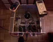
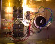
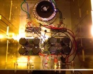
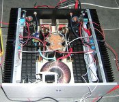
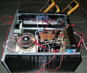
My second F5. Only one transformer this time. Used Hexfreds and Caddocks.
No thermal or protection circuit. Sounds great!
My second F5. Only one transformer this time. Used Hexfreds and Caddocks.
No thermal or protection circuit. Sounds great!
Attachments
Last edited:
I once experienced amp module burst into flames,
Papa would be proud!

Ron
Trouble with biasing one channel
Try as I might the only way I can get dc offset on one of the channels to acceptable levels is at about 0.35v on the output resistors. The other channel is fine and to spec. I did hook up the mosfets wrong on the problem channel at first and had some smoke and fumes, but I replaced all the 3w resistors including the feedback ones which I thought I saw the overheating and fumes coming from. The music plays fine at this lower bias and the output levels are comparable to the other channel. In fact imaging and balance are precise.
The two questions I have are -
What other part could've been damaged causing the biasing issue? In real terms does having a lower bias simply mean that I'll hear the poverbial 'klunk' a little earlier on that channel? Especially if I cannot hear a perceptible difference in sound quality.
Thanks
My second F5. Only one transformer this time. Used Hexfreds and Caddocks.
No thermal or protection circuit. Sounds great!
I'm wondering the ratings on that transformer you are using as I could not find a suitable transformer for stereo operation.
Try as I might the only way I can get dc offset on one of the channels to acceptable levels is at about 0.35v on the output resistors. The other channel is fine and to spec. I did hook up the mosfets wrong on the problem channel at first and had some smoke and fumes, but I replaced all the 3w resistors including the feedback ones which I thought I saw the overheating and fumes coming from. The music plays fine at this lower bias and the output levels are comparable to the other channel. In fact imaging and balance are precise.
The two questions I have are -
What other part could've been damaged causing the biasing issue? In real terms does having a lower bias simply mean that I'll hear the poverbial 'klunk' a little earlier on that channel? Especially if I cannot hear a perceptible difference in sound quality.
Thanks
You'll have to give us other voltage readings (measure where Vdc are indicated on the F5 schematic) for us to have a better idea of what's going on. Check your input fets for shorted D-S --a 0Vdc reading indicates a short. Check for output Vdc offset value.
I'm wondering the ratings on that transformer you are using as I could not find a suitable transformer for stereo operation.
I used an Antek AN-4218.
Antek - AN-4218
Search for the group buy number here and you get $10 off at purchase, email John at Antek and ask if it is still on. I don't know if it is.
What about the pots? Did you check them before putting them in? With the amp off, and power removed from the amp board if possible, measure across R3 and R4 (2.2k) while adjusting the pots for each side of the PCB. You should get around 1.5k max. I think the pots should be at zero before applying power again.
Found that because the leads were short on the Bourns pots and usig large gauge solder, I had a cold solder. One side of the PCB was not registering any resistance when adjusting the pot.
Found that because the leads were short on the Bourns pots and usig large gauge solder, I had a cold solder. One side of the PCB was not registering any resistance when adjusting the pot.
Last edited:
I think the issue is with one of the pots. I see little variation in voltage when turning it. I had used bourns multi-turn ones because I thought it would provide finer control but they really are very inconvenient to use. Let me replace them all with single-turn types and see if I can resolve this.
btw I checked the voltages across the various components and they compare well with the good channel except for the output resistors and offset. Also the transistors checked out fine.
btw I checked the voltages across the various components and they compare well with the good channel except for the output resistors and offset. Also the transistors checked out fine.
It's alive !!!
It's alive !!! It's alive !!! And this time it's not a monster
Finally I have finished my F5 built, after following this thread for a long time and collecting parts it's now playing and it sounds very very good.
What's inside:
- 500VA Toroidy transformer MUR3020 for the bridge
- CLC power supply: 47000uf -> 10mH chokes -> 2x22000uF sikorels
- F5 simplified circuit without temperature tracking, current limiting and with reduced feedback (2x150ohm) à la Peter Daniël.
Fairchild transistors, Mills MRA5, Takman REY and TX2575 z-foil resistors.
- circuit ground connected to mains earth trough a loop breaker circuit, case of course connected to mains earth.
- soft start based on CL60 and circuit from Sylvain Bergeron.
The soft start has its own small transformer and power supply, the switch on the front panel activates the soft start:
a double relay is switched on that puts the mains on the 500VA transformer with a thermistor CL60 in series,
after two seconds that thermistor is bypassed with a second relay, so that the mains is directly connected to the 500VA.
I's nice to hear the sound of the relays clicking
- DC protection based on upc1237: basic circuit like in the datasheet. DC protection, time delay at power on and AC level detection.
For the upc1237 and the 24vdc relays I needed a higher voltage than my rail voltage(24vdc),
so I added a voltage doubler (the 4X8) that gives me 48vdc.
loudspeaker relays are the LRZ from amplimo: first a contact that can switch 100A (at 50V) is closed, after that the contact is bridged by a gold plated silver contact.
I'm very satisfied with this amplifier, my other reference is a two stage DIY KT88 PushPull with interstage transformer as phase splitter,
compared to the KT88 gives the F5 better detail but a little less bas. The F5 gives me more the feeling of being there, I like the F5 more
Thank you Nelson for such a nice amplifier !
Regards,
Danny
Attachments
Last edited:
500VA,MUR3020, CLC, 47000uf, 10mH, 22000uF sikorels, Mills MRA5, Takman REY, TX2575, CL60, small transformer, double relay, second relay, upc1237, voltage doubler, LRZ.
Merde de putana.
.Does cooling get double if i cut this heatsink in a half ?
Is it reliable to attach one transistor to one cooler and other transistor to other cooler ?( I mean heat balance)
Theres often confusion about what is length, width and hight on a heatsink
It should be looked at like a long chunk of aluminium, laid flat on its base, ready fore cutting
Which means, length of heatsink will be height of amp box, funny eh
Height is the finning size
But it has been stated previously that a very long heatsink(box height) is less efffective, than cutting it in half
It goes without saying that each half will hold just one transistor each
I believe the gain could be up to 50% better
But depends on transistor mounting and type of heatsink
Every heatsink type has its own certain optimal "length"
Anything longer that this optimal max size is just waste
I think the better wide ones reach their optimal max around 200-250mm long
Many smaller width heatsink types reach their optimal max size at shorter length, like maybe 100-150mm
Yes, its reliable
- Home
- Amplifiers
- Pass Labs
- F5 power amplifier