The last graph already shows the thermal resistance of the heatsink.
(thermal dynamics 101 : the thermal resistance number depends on the temperature difference between heatsink and ambient. The higher the temp difference, the higher the efficiency of the sink) <snip>
Maybe I am upside down on this but if the temp diff between the heatsink and the ambient is nil, then the transfer is very very good. If the temp diff is very high then the transfer is very very poor??
So the lower the temp diff the higher the efficiency?
_-_-bear
Fozzy Bear,
does the refrigerator in your kitchen have to work hardest in winter or summer ?
ya Dutchiewhale - how on earth he can know that ?
he's sleeping during winter

how does this affect the exposure calc?
Means it's a nice catch.
Fig 13 shows that Applied power to LED is dissipation, 55W for 34C temperature rise corresponds to 0.62 C/W in Fig 12.
I want one myself. Skip that, i want two.
Means it's a nice catch.
Fig 13 shows that Applied power to LED is dissipation, 55W for 34C temperature rise corresponds to 0.62 C/W in Fig 12.
I want one myself. Skip that, i want two.
Wouldn't you need 4? One per each device on each channel?
1 on 1 would enable to raise the bias current to about 2A.
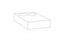
But such a heatsink needs something to suspend it in mid-air for it to be effective, with open passageways on both sides.
The requirement to couple the heatsink to a fixture makes a combined thermal resistance possible that's significantly lower to drop the heatsink count to 1 per channel, 10% is easy to obtain.
Add-ons can range from an alloy column, which also seats the output devices, to a length of pipe that acts both as fixture, heatsink and duct-convector.
I think you guys are reading the datasheet wrong. At about 55W to the LED the heatsink is around .6W/C. The LEDs that are shown in that datasheet are between 75% and 85% efficient. So they are not dissipating 55W of heat into that sink. The sink would be perfect (well maybe not 'perfect') for one mosfet each if there was a slight amount of air blowing across it.
With 40W of power applied to the LED there is a 25C increase above ambient.
Uriah
EDITING: Its not the LED that is 75-85 efficient.. its the Optics/Lens that is efficient it seems. I am looking up some of the LEDs they recommend. But anyway LEDs are not 0% efficient so we are not dumping 55W into the sink.
Last edited:
The datasheet doesn't mention a lot of things, such as the position the heatsink is in, could be worst case measurement.
If the core of that thing is indeed solid, performance in horizontal position will be a lot better imo, judging by the length and number of fins.
IF the core is solid, i still doubt it because the heatsink would then weigh 3lbs or more each, hollow is more likely.
If the core of that thing is indeed solid, performance in horizontal position will be a lot better imo, judging by the length and number of fins.
IF the core is solid, i still doubt it because the heatsink would then weigh 3lbs or more each, hollow is more likely.
I called and left a message with them. We will see if they call back. There is a 1" thick model that they have where the DO give the specs we need. They give the spec with regard to the heat dissipated into the sink rather than the power applied to the LED. But on the model we are looking at HS-5430-0537 they only give the temp of the sink with regard to power applied to the LED and since we dont know efficiency of LED this doesnt help a lot.
Uriah
Uriah
Might be they would work
But I suppose you wouldnt normally dream of using just 3" height fore F5
So Im with Udailey, at least one pr device
But man, alone the trouble of doing a nice design and assembling with those
It will look like spaceship ufo
But hey, if you like that, it will be just right
But I admit, they are interesting, somehow
Maybe if you could hardwire the devices they could be mounted reversed at the center ends
And they could go through holes in the top plate
That could look quite nice
But it would all need to be assembled from the bottom, upside down
Might actually result in very effective convection cooling
Attachments
Might be they would work
But I suppose you wouldnt normally dream of using just 3" height fore F5
So Im with Udailey, at least one pr device
But man, alone the trouble of doing a nice design and assembling with those
It will look like spaceship ufo
But hey, if you like that, it will be just right
But I admit, they are interesting, somehow
Maybe if you could hardwire the devices they could be mounted reversed at the center ends
And they could go through holes in the top plate
That could look quite nice
But it would all need to be assembled from the bottom, upside down
Might actually result in very effective convection cooling
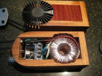
Or, It could look somthing like this... one of Peter Daniels gainclone kits I made using one of the other heat sinks this company makes.
Attachments
Fozzy Bear,
does the refrigerator in your kitchen have to work hardest in winter or summer ?
Summer of course...
But, in the winter the temp difference between the innards and the outards may be zero, or negative... so the refrigerator appears to have fantastic efficiency!
(I suspect that within bounds the efficiency of the refrig remains unchanged - the actual losses change with outside temperature differential compared to the inside...)
There is a difference between the internal thermal conductivity of a material (like an aluminum heatsink) and its ability to conduct heat out to the environment.
For a given heatsource, it seem logical that IF that heat source of a fixed BTU output is spread over a greater area evenly, then the temperature per area is going to be lower not higher?
The more effective heatsink will have a lower temperature than one with less effectiveness. Can we call this efficiency?
_-_-bear
Last edited:
Or, It could look somthing like this... one of Peter Daniels gainclone kits I made using one of the other heat sinks this company makes.
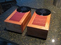
Very very nice erpiii! Although I must say to let the hsink sit atop if you use it for class a as the wood reduces the hsink's effective area.
...........the wood reduces the hsink's effective area.
On the contrary, if you think concevtion cooling
Well, ok, yes, if you are looking at backplate, it does seem to be under the heatsink, which wont be good
But the wood might burn


On the contrary, if you think concevtion cooling
Well, ok, yes, if you are looking at backplate, it does seem to be under the heatsink, which wont be good
But the wood might burn
And half of the outer circumference too...
Very very nice erpiii! Although I must say to let the hsink sit atop if you use it for class a as the wood reduces the hsink's effective area.
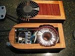
The amp in the top of the picture is right side up... the amp at the bottom of the picture shows thew underside of the amp with the bottom removed.
This is how they look in use.
Attachments
Last edited:
I once experienced amp module burst into flames, literally
And it was a famous proven design, but known to be occationally unstable
I wont mention any names
Fortunetely I smelled it, and nothing happened
I use wood too
But its a good question if we really should be using wood at all
Sorry if it appears negative
Such things never happens, but you never know
Just a word of caution
- Home
- Amplifiers
- Pass Labs
- F5 power amplifier