most of the rest of the world in their ignorance just fit the biggest fuse they have in the drawer. If it's 15A it must be better than 3A!!Still I wonder what the rest of the world does with such a transformer... Can`t possibly line up 3 thermistors just to get this beast started? Sigh.
The standard fuse for an inductive load is Fuse rating ~= VA / Vac * 3
Your 300VA can use a 300 / 220 * 3 = 4.1A. Use a T4A fuse.
That fuse will pass 4A almost forever and pass 8A for many minutes in a fault situation.
I don't want 220 * 8 = 1.75kW being dissipated in a faulty piece of equipment in my house. Not even for a few minutes.
I promote the use of close rated fusing. That demands that inductive loads use some form of soft start.
Mmm, following all the calculations I get dazzled even more.
I have looked up some really heavy duty thermistors (25amp) but those are 2 ohm. Still creating too much inrush current.
The best I can find are 10 ohm 15amp, at farnell, from Ametherm (ms3210015)
Like Udaily said, putting them in series doesnt do anything for the maximum current of the thermistor (stupid me") ) it will just lower the inrush current, but I will still end up with to small thermistors (when using the cl60`s or other lower rated ones)
) it will just lower the inrush current, but I will still end up with to small thermistors (when using the cl60`s or other lower rated ones)
To prevent my project comming to a halt, I want to order 2 from Ametherm at Farnell, they have 10ohm res, and can handle 15 amp. I also looked at a softstart, but those are out of stock. And building it myself creates extra complexcity for my already tortured grey mass...
Unless anyone thinks it not wise to do it like I intend, I will parallel two of the Ametherms. Using one would even be better, but don`t know if thats a wise thing to do.
Thanks for helping a newbie
I have looked up some really heavy duty thermistors (25amp) but those are 2 ohm. Still creating too much inrush current.
The best I can find are 10 ohm 15amp, at farnell, from Ametherm (ms3210015)
Like Udaily said, putting them in series doesnt do anything for the maximum current of the thermistor (stupid me
) it will just lower the inrush current, but I will still end up with to small thermistors (when using the cl60`s or other lower rated ones)To prevent my project comming to a halt, I want to order 2 from Ametherm at Farnell, they have 10ohm res, and can handle 15 amp. I also looked at a softstart, but those are out of stock. And building it myself creates extra complexcity for my already tortured grey mass...
Unless anyone thinks it not wise to do it like I intend, I will parallel two of the Ametherms. Using one would even be better, but don`t know if thats a wise thing to do.
Thanks for helping a newbie
I get somewhere between 200mV and 300mV at the output.
That is with +/-35 V rails and 2.4A bias
One open rail.
I remember now that i experimented this by (bad) chance. Nothing happened.
I couldn't believe it at this time. I still do not understand why it is.
Could anyone explain this?
Last edited:
if your secondary peak voltage is 60V and the capacitance acts like a short circuit at start of charge then a 10r will limit the initial charging current to 6A. What's the problem? As the capacitor charge/voltage rises the current will fall (rapidly), but also the Thermistor is heating due to the 60W (6A & 10r) of dissipation and it's resistance drops. The combination of rising voltage in the capacitor bank and the dropping resistance of the thermistor try to maintain a near constant charging current (well not even close to constant, but a lot better than the exponential charging rate if no limiter were fitted).I can find are 10 ohm 15amp, at farnell, from Ametherm (ms3210015)
After a period the caps will be upto near 90% of final voltage and the thermistor resistance will have dropped to a couple of ohms, now bring in the bypass relay to finally charge the cap bank using just 10% of the intial charge voltage resulting in a 10fold reduction in peak charging current.
DO NOT use a voltage comparator for the bypass relay control. If mains voltage is low or a fault has developed in the load then the caps may never reach 90% of full nominal voltage and the bypass relay would never pull in.
This is especially important with resistor limiters which will burn out if held in circuit for longer than required.
I dont know, but
I've used CL60 and the Siemens B57364 equivalent for toroidals up to 1000VA, with as low as 12Vac secondaries for a variable lab power supply, can't recall ever to have bothered to use other than a single NTC.
A 500VA/230V requires a T2.5A or larger slow blow fuse, imdorko.
In manufacturer writing : www.amplimo.nl/download/870xx.pdf
Last edited:
I get somewhere between 200mV and 300mV at the output.
That is with +/-35 V rails and 2.4A bias
Interesting, thanks!
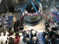
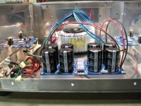
Finishing up on the F5 build and thought some might like to see the efforts. The fact that a Caveman like myself can build one of these and have it sounding good and looking fairly decent speaks volumes about the ease of construction and the elegance of the design.
Big thanks to Nelson Pass for releasing the design and allowing some of us into the world of Class A.
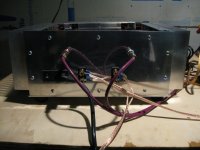
The chassis is a DIY, all aluminum construction. The heatsinks are from M&M metals. I'm still working on the faceplate. It will be polished just like the backplate and sinks. I just can't stop listening to start on polishing, again.
Big thanks to Nelson Pass for releasing the design and allowing some of us into the world of Class A.
The chassis is a DIY, all aluminum construction. The heatsinks are from M&M metals. I'm still working on the faceplate. It will be polished just like the backplate and sinks. I just can't stop listening to start on polishing, again
.Attachments
My fellow DIYers and especially bobodioulasso , I'm sorry to bother you with my n00b-tastic PSU questions, but the more I think about it, the more I'm concerned. Anyhow, I'm trying to use a transformer from an Adcom GFA-1 amp, I measured 66v on the secondary, and thinking if I can get two separate +/- 22v supplies for my 2 channels of F5 amp respectively. Would it work like this, with a center tapped winding, as opposed to two separate secondaries?
An externally hosted image should be here but it was not working when we last tested it.
Last edited:
Hello
I would like to ask for some help .
I'm planning to use multiple power mosfet , actually 3 pair Toshiba power mosfet in my F5 without the current lim. for higher power with 36V rail power supp .
Do I have to use thermistor , if yes one pair is enough for one channel or I have to use as many like mosfet .
If I need one thermistor to each mosfet the thermistor value have to be 4.7K .
Or just go for it with out thermistor ?
Thanks for the help
Greets
I wouldnt take any risks with those expencive Toshibas
I have just bought Renesas, so I have the same worries
I have decided to keep it at 28V or 30V, with sligthly higher bias
Neither I have decided on the thermistors yet
Just a thought, but have anyone ever considered matching the thermistors
How accurate are they
Could the thermistor actually cause imbalance
Could that be one reason why people think it sounds better without
Last edited:
I purchased thermistor before just 200R for another project. I selected them in the store from 160R to 220 it was everything there .
It took me at least 20 min. to find 4 piece 200R.
I will go with 36V rail (3 pair per channel , must work) , probably with lower bias. Some people built Aleph4 only 3 pair power mosfet . Aleph4 running over 45V rail. 3 pair have to take the heat with the right size heat sink!!!
I just don't know if someone built F5 with out current lim. and with out thermistor.
Is to long to read all .
If is OK with out thermistor , I do not want to use them .
From Renesans you get Lateral mosfet or Vertical .
Someone already tried lateral verizon but in these circuit doesn't work.
Greets
I think your Toshibas are laterals too
I believe Renesas bought the Toshiba patent
Yes, it have been done without limiter and thermistors
There have been several reporting not to set nias too high without
Bias seem to get unstable at a certain point
I might suspect that more efficient cooling and/or heat transfer would improve on this
With raised voltage you need to cacode the Jfet
It have been showed how, some posts back
Last edited:
Hello
Yes I go with cascode . My Toshiba mosfets are Vertical .
Renesans bought the Hitachi patent .
I know because I built similar amp like F5 with Lateral mosfet . The Profet .
It is a great amp !
The reason I want to try F5 .
Be careful if you get Lateral mosfet those are no good here !
I also have 10pair orig. Hitachi lateral but with Lateral mosfet F5 does not working !!
Greets
Attachments
boyz
maybe - before throwing any amount of money or energy in it - is wise to re-read Papa's pdf few more times ?
just one thermistor per rail ; it's temperature sensitive input jfet's drain resistor , nothing else .
go back in thread and look for several already made F5s with laterals in output
if I remember - jackinnj made at least pair of them
Thanks Zen
I have to tell the truth I didn't read the tread all the way .It would take days!!!!!!!!!
All I remember right at the beginning someone tried with 3 pair lateral but to him didn't work to him .
To him the power mosfet(s) heat up very fast .
I do not want to mislead nobody .
If already was sucsesful built with laterals that great news .So go on and build it .Don't forget Renesans lateral 2SK1058 /2SJ162 only 7A .
I prefer laterals over vertical mosfet . Of course not from Renesans , Exicon much better even the orig Hitachi better to my ear .I tested them in my Profet amp .
But now is to late , I made my PC board layout to use the Toshiba vertical mosfet .
I think Toshiba is not bad either .Of course they are very expensive but I already have them .
Thank one more time Zen
Attachments
polishing
Hey westend,
Are you polishing the aluminum by hand? I hand polished aluminum for an amp build about 2 years ago -- it took for ever and it was hell.
How did it go for you?
Steve
It will be polished just like the backplate and sinks. I just can't stop listening to start on polishing, again
Hey westend,
Are you polishing the aluminum by hand? I hand polished aluminum for an amp build about 2 years ago -- it took for ever and it was hell.
How did it go for you?
Steve
My fellow DIYers and especially bobodioulasso , I'm sorry to bother you with my n00b-tastic PSU questions, but the more I think about it, the more I'm concerned. Anyhow, I'm trying to use a transformer from an Adcom GFA-1 amp, I measured 66v on the secondary, and thinking if I can get two separate +/- 22v supplies for my 2 channels of F5 amp respectively. Would it work like this, with a center tapped winding, as opposed to two separate secondaries?
An externally hosted image should be here but it was not working when we last tested it.
Aren't your two grounds at different potentials?
...You need two separate secondary windings, i think.
Last edited:
- Home
- Amplifiers
- Pass Labs
- F5 power amplifier