AndrewT said:could somebody be more specific.
I went back 5pages ........
Zen Mod said:
go back to FIRST 5 or 6 pages
Re: Re: Re: Re: newbie need help
 woooooowww.......toroid 16A or 20A. how much it cost in your country??
is there someone from singapore, ausey or new zealand (they're the close one).
if i buy this toroid and send to my country indonesia, who much it cost?? (toroid+shipping)
thank you.
labjr said:
That's 8-10 amps per winding. You're going to need a transformer that is capable of twice that at 16 to 20 amps.
woooooowww.......toroid 16A or 20A. how much it cost in your country??is there someone from singapore, ausey or new zealand (they're the close one).
if i buy this toroid and send to my country indonesia, who much it cost?? (toroid+shipping)
thank you.
Re: Re: Re: Re: newbie need help
woooooowww.......toroid 16A or 20A. how much it cost in your country??
is there someone from singapore, ausey or new zealand (they're the close one).
if i buy this toroid (220V/18-0-18/20A)and send to my country indonesia, who much it cost?? (toroid+shipping)
thank you.
labjr said:
That's 8-10 amps per winding. You're going to need a transformer that is capable of twice that at 16 to 20 amps.
woooooowww.......toroid 16A or 20A. how much it cost in your country??is there someone from singapore, ausey or new zealand (they're the close one).
if i buy this toroid (220V/18-0-18/20A)and send to my country indonesia, who much it cost?? (toroid+shipping)
thank you.
Re: Re: Re: Re: Re: newbie need help
John at Antek sends them via Global Priority Mail "Flat Rate Box" -- they've upped the price recently, but you can fit 20# (9kg) for $42 almost anywhere in the world.meemee said:......toroid 16A or 20A. how much it cost in your country??
is there someone from singapore, ausey or new zealand (they're the close one).
if i buy this toroid (220V/18-0-18/20A)and send to my country indonesia, who much it cost?? (toroid+shipping)
thank you.
I just talked to a guy at Wakefield. He says that those microfins on the heatsinks regular fins dont come into play in natural convection AT ALL. Not in any way are they considered part of the total surface area. He says they need 600LFM or was it CFM, anyway they need a lot of air before they are an advantage.
Uriah
Uriah
zen5 (for F5) power supply with V reg - need help
Hi all,
The AC voltage at my house varies quite a bit (114V RMS ot 126V RMS). And the rail
voltage and DC offset on my (diy) F5 varies with it. So I thought I would try modifying
my Zen5 based power supply to use feedback and see if that gave me more stable
rail voltage.
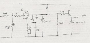
My plan was to use LM317/LM337 IC adjustable voltage regulators in place of the zener
diodes to control the mosfets used for regulation. I've included a diagram of the circuit
for the positive side.
My problem is that at best, my regulated output voltage is about 10V less than my
unregulated voltage. I'm sure I've done something wrong, but I can't see it. Would
anyone care to offer any help or insight?
Again, this circuit is (was) the Zen 5 power supply. I have not shown the parts before
the inductor coils, as it is the same as the Zen 5. In my case, I get about 28V. The
max voltage I get after the LM317 is 18V.
There is a lot that I don't understand about this (and the stock) supply. I think the
1K resistor is a current limiting resitor for the (removed) zender diodes. As this part
of the circuit doesn't use much current, it seemed reasonable to keep them. Nelson
mentions that the diodes are to quickly drain the 2200uF caps, but I don't understand
how they do that. I guess they also somehow act as flyback diodes for the coils too
(and I don't understand that either), so I decided to keep them. I think the diode on
the input side of the regulator is for flyback purposes, and the diode on the output side
of the regulator is to drain the 2200uF caps.
The LM317 requires a current load of at least 3.5mA, The 2.6K resistor was supposed
to supply that (when at 26V).
Could someone please give me a hand with this?
thanks,
Robert
Hi all,
The AC voltage at my house varies quite a bit (114V RMS ot 126V RMS). And the rail
voltage and DC offset on my (diy) F5 varies with it. So I thought I would try modifying
my Zen5 based power supply to use feedback and see if that gave me more stable
rail voltage.
My plan was to use LM317/LM337 IC adjustable voltage regulators in place of the zener
diodes to control the mosfets used for regulation. I've included a diagram of the circuit
for the positive side.
My problem is that at best, my regulated output voltage is about 10V less than my
unregulated voltage. I'm sure I've done something wrong, but I can't see it. Would
anyone care to offer any help or insight?
Again, this circuit is (was) the Zen 5 power supply. I have not shown the parts before
the inductor coils, as it is the same as the Zen 5. In my case, I get about 28V. The
max voltage I get after the LM317 is 18V.
There is a lot that I don't understand about this (and the stock) supply. I think the
1K resistor is a current limiting resitor for the (removed) zender diodes. As this part
of the circuit doesn't use much current, it seemed reasonable to keep them. Nelson
mentions that the diodes are to quickly drain the 2200uF caps, but I don't understand
how they do that. I guess they also somehow act as flyback diodes for the coils too
(and I don't understand that either), so I decided to keep them. I think the diode on
the input side of the regulator is for flyback purposes, and the diode on the output side
of the regulator is to drain the 2200uF caps.
The LM317 requires a current load of at least 3.5mA, The 2.6K resistor was supposed
to supply that (when at 26V).
Could someone please give me a hand with this?
thanks,
Robert
Attachments
Re: zen5 (for F5) power supply with V reg - need help
It seems that 1k and 2.6K are acting as a voltage divider.
That is the "in" voltage of LM317 seems to be only about 28*2.6/3.6= 20V.
>>") <<
<<
audiorob said:
In my case, I get about 28V. The
max voltage I get after the LM317 is 18V.
It seems that 1k and 2.6K are acting as a voltage divider.
That is the "in" voltage of LM317 seems to be only about 28*2.6/3.6= 20V.
>>
<<quote:
you will want to find some way to make sure that it indeed makes good contact with the heatsink rather than having a slight warp in it that would cause an airspace.
For this reason Thermal paste between the copper and Alu sink also Iwould think.
W-Fran,
I used a 6"square aluminum tube for my heatsinks on my F4. (each one is a stereo amp run balanced)
3/16" wall thickness, but 1/4" would have been better for one of the reasons we discussed here- spreading the heat! I made it the same square inches as the Pass F4's (as mentioned make sure to account for whether both sides are exposed to cool air) plus 20% and the area is plenty but some areas are only warm..I'm sure the stack configuration helps... There is a hole in the top and bottom wood plates.
The aluminum was about $120 for two of the towers. If I had it to do again I would use 1/4"instead of 3/16" walls and not make them 20% bigger than the Pass area. The current tubes are 30" tall, 24" would be fine if 1/4" thick. The cost would have been the same because the surplus place sells by the pound.
Not a particularly cheap surplus place though..
An externally hosted image should be here but it was not working when we last tested it.
Variac said:
Beautiful
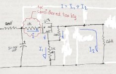
I think that the content in post #2970 is incorrect regarding the voltage divider because there are other resistors than 1K and 2.6K . . .
Anyhow, the 1K is considered too big because there will be voltage drop across 1K when current flows through it.
Simplified sketch is drawn to help my poor head with a simple picture, and attached here. . .
Cheers,
>><<
Anyhow, the 1K is considered too big because there will be voltage drop across 1K when current flows through it.
Simplified sketch is drawn to help my poor head with a simple picture, and attached here. . .
Cheers,
>>
<<Attachments
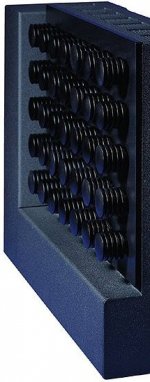
Variac said:again steampunk
The Tower of Power.
(i'm still waiting for the petrolhead who used Hemi-D aluminum cylinder heads)
Did someone say microfins ?
Attachments
rhysh said:I have just powered up my f5, just the PS. I am using 1.25A fuses on 230v mains. I have tried three times and the fuse blows every time.
Could this be the inrush current of the transformer? The fuse will blow when the transformer alone is connected.
Are you using a thermistor in the power supply? Are you using a slow-blow fuse? How much capacitance is in your power supply?
labjr said:
Are you using thermistor in the power supply? Are you using a slow-blow fuse? How much capacitance is in your power supply?
No thermistor as of yet, its awaiting delivery at my supplier. Using a slow blow 1.25A fuse with 176,000uf capacitance.
rhysh said:
No thermistor as of yet, its awaiting delivery at my supplier. Using a slow blow 1.25A fuse with 176,000uf capacitance.
Long while back, I put an on/off switch across the Live/Neutral instead of in series with the live.
Blew the fuse everytime

- Home
- Amplifiers
- Pass Labs
- F5 power amplifier