Re: Power supply
Regarding the active regulator for class A amps, please read this:
http://www.passdiy.com/pdf/zen-ver3.pdf
You know...? I want to get rail voltage of 23~25V as Papa has said that in this rail voltage range he has got best result. Sure, I'd like to enjoy his experience. In addition, I want to use the EI trans which I already have. But, it has secondary voltages of 25Vac-0, which would give me the rail voltage of about 32Vdc if I use the standard CRC filter. 32V... too high. Hummm... I want to have the rail voltage of abot 23V and at the same time want to use this trans... What should I do? I think that an idea is applying the active regulator to cut off some upper part of dc voltage to make the rail about 23Vdc. If there are other benefits with the active regulator, they are ...
...
Actually, I have already mentioned about this somewhere in this thread.
Cheers,
enzedone said:
Why not use the standard one offered in the service manual?
Is it that you are after a regulated power supply? and why do think they are better?
Regarding the active regulator for class A amps, please read this:
http://www.passdiy.com/pdf/zen-ver3.pdf
You know...? I want to get rail voltage of 23~25V as Papa has said that in this rail voltage range he has got best result. Sure, I'd like to enjoy his experience. In addition, I want to use the EI trans which I already have. But, it has secondary voltages of 25Vac-0, which would give me the rail voltage of about 32Vdc if I use the standard CRC filter. 32V... too high. Hummm... I want to have the rail voltage of abot 23V and at the same time want to use this trans... What should I do? I think that an idea is applying the active regulator to cut off some upper part of dc voltage to make the rail about 23Vdc. If there are other benefits with the active regulator, they are
...Actually, I have already mentioned about this somewhere in this thread.
Cheers,
Babowana said:Not any comment from you. . . ?
Okay, waiting your comments, I have pondered whether having of only one C1 (33,000uF) at the entrance to the active regulator is enough for the size as a filtering cap. Mmm. . . enough or not. . .?
I think I go with this version dated 11NOV2008.
Cheers,
")
JH, good work on that schematic. Thats a fine PSU. (I see you corrected one of papa's rare mistakes in fig.6
)You can actually get away with using much smaller caps for C3-C6. Having a couple of those big ones free, you could consider a C-R-C in front of the reg's. Just a thought, I am sure your design will work great. Good call, having seperate reg's for each channel.
BTW, your designator L+ at the negative leg should read R-.
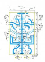

Babowana said:I finished fabrication of the PSU board as in the post#204, except that I used the bleeder resistors, R1 & R2 (ref. to post #109) of 2W-rating, not 3W. Hope this would be no problem.
Cheers,
Looks good, JH. That was fast, nearly as LL
Good luck powering up, the thing.
Thanks.
Yeah~ true, it's fast. I very often do not like waiting
You know? I will finish soldering of the amp boards of both channels tomorrow.
But, but . . .
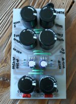
I can't handle heavy work myself. For the time being, I don't have any physical power. I wonder how I could diy the chassiss by myself. I'm thinking to use the old chassiss of Babo Zen or Zen V2-X. However, I don't want to destroy these amps. I really want to keep them. Then, only thing I could do is . . . I should order new chassiss including heat sinks to a shop . . .
I would visit the shop tomorrow morning for a discussion to estimate a budget . . .
Cheers,
Yeah~ true, it's fast. I very often do not like waiting
You know? I will finish soldering of the amp boards of both channels tomorrow.
But, but . . .
I can't handle heavy work myself. For the time being, I don't have any physical power. I wonder how I could diy the chassiss by myself. I'm thinking to use the old chassiss of Babo Zen or Zen V2-X. However, I don't want to destroy these amps. I really want to keep them. Then, only thing I could do is . . . I should order new chassiss including heat sinks to a shop . . .
I would visit the shop tomorrow morning for a discussion to estimate a budget . . .
Cheers,


You will get much better knowledge than I have
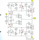
Here I am re-drawing F5 circuit with component values I have.
- Increased R3, R4, R15 and R16 to 2.4K
- Increased TH1 and TH2 to 5K
- Reduced P1 and P2 down to 2K
These will provide me with adjustable resistance value of 0~950ohms between the +rail and the drain of Q1 and between -rail and the drain of Q2. So, these changes should be okay.
- Changed Q1 to 2SJ74 and Q2 to 2SK170
- Increased R19 and R20 to 160 as I have number of this resistor. This will provide the amp with reduced max. output current of about 9A.
- Increased R21 and R22 to 18K. Papa recommends 22K, but I have only 18K of the value near to 22K.
- Changed R5, R6, R7 and R8 to 2W-rating as I have number of 100ohm-2W resistors
I will go ahead with the re-drawn . . .
Cheers,
Attachments
enzedone said:
I will probably increase R21 & R22 as well, but that will be about for me.
I wonder . . .
R21 and R22 are arranged to prevent too much power dissipation in the Mosfet in case the output is shorted by mistake and the short current exists during certain time length. Nevertheless, Papa recommends to increase R1 and R2, saying that it's for a marginal better sound. (Sacrificing the better safety of the short circuit . . . ?)
>>
 <<
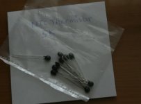
<<I misunderstood myself as I had TH1 and TH2 of 5K ohms. I was wrong. So, I tried to find 5K ohm thermistors from few dealers located near to my place, but . . . but . . . uhhhhm . . .
>>
<<I'm thinking to replace 5K ohm thermistors with 10K which is easy finding here for me.
Cheers,
>>
PositiveWay<<NTC Thermistors
I found these ones at Farnell
Part No.
RL1004-2910-97-D1
http://nz.farnell.com/ge-sensing-thermometrics/rl1004-2910-97-d1/ntc-thermistor/dp/9771336
What Value Thermistor are you using on the power supply/Star ground? I was told about 25 Ohms should be o.k?Edit: Just found these:
http://nz.farnell.com/ge-sensing-thermometrics/cl-70/ntc-thermistor/dp/1707188
If you can't order them, let me know and I will put an order in for you from here, and wack them in the post for ya.
Re: NTC Thermistors
I am using CL-60 type (5 ohms/10A) between the star ground and the power socket earth point.
Thanks for your kind offer
But, sure, I can order the 5K ohms zener from here to Farnell. I just thought of easy mwthod . . . Tks again!
Cheers,
>><<
enzedone said:
What Value Thermistor are you using on the power supply/Star ground? I was told about 25 Ohms should be o.k?Edit: Just found these:
If you can't order them, let me know and I will put an order in for you from here, and wack them in the post for ya.
I am using CL-60 type (5 ohms/10A) between the star ground and the power socket earth point.
Thanks for your kind offer
But, sure, I can order the 5K ohms zener from here to Farnell. I just thought of easy mwthod . . . Tks again!
Cheers,
>>
<<
- Status
- This old topic is closed. If you want to reopen this topic, contact a moderator using the "Report Post" button.
- Home
- Amplifiers
- Pass Labs
- ATC SCM7 . . . with Papa's diy amp?