Yeah, I know that I was slow..He-he Sometimes a man needs a break.... Not that I did.. but.... confusing enough?? Figure it out yourself...He-he again. Here is the main reason for being slow lately: Greek Grillmeister makes even ZM look small...He-hempmarino said:
...will the commercial version come with a roll of battery holder?
Steen, Would you say that this compares favorably with others - the X-Bosoz in particular. I know it is still early... but it took you long enuff to get one together
edit:
--or look for discounted/obsolete/new cordless drill packs at the home center")

The sound of the J-fet-BoZ is just great. If you doesnt need balanced in/out look no further, if you are into the low count components category. Further impressions to come along!
Steen
Attachments

steenoe said:
...................If you doesnt need balanced in/out look no further, if you are into the low count components category. Further impressions to come along!
Steen
yeah.........investing in two additional jfets ,four more resistors and one more stereo pot - to have bal in -out (with condition that output load must be highish) will break a bank..............
that's for this picture!!
 now all is back to normal in the world again, congratulations Steenoe!
I am still having problems with my testing (still getting alot of distortion from external dac as source - running from laptop headphone output is nice and clear, probably due to the puny mV output from the computer jack). I'm also trying to figure out why I am no longer getting any attenuation from my (input) pot - I've tried 20K and 10K, but no luck


I've also moved off the gainclone for testing to F4, so after hearing Steenoe's comment, I'm even more anxious to get this working ... wish me luck
Stephen
I find this one of the most surprising threads for a while.
The circuit is an exact replica of my beloved MC stepup from about 10 years ago. At that time i also tried the Pacific riaa (ok, it lacks source resistors) but the output distortion, although pleasing was a bit too much to swallow.
Now, it's sudddenly capable of producing an output of many volts with no distortion at all.
Btw, using batteries is cheating.
analog_sa said:I find this one of the most surprising threads for a while.
..............
Joelist?
Thorsten?
"Hi there,
>You had spoke about building this preamp. Do you have a schematic available
>for it? If so can you please send it if possible.
Here is what I have. All ASCII I'm afraid....
l'Audiophile MC Pre-Pre
=======================
Folks, with just few resistors, one JFET, one output cap you can build a
step-up device.
12 Volts regulated or accumulator buffered supply
|
|
2k2
|
|---------0.47uF-----out------------>
| |
(drain) |
---in---------(gate)JFET 100k
| (source) |
100R | |
| 47R |
| | |
-ground--------------------------------------------------
The basic topology is that of the second step-up amplifier by "Maison de
L'Audiophile" of Paris/France.
The first 100R is the cartridge load, which must be adapted for the
cartridge you use. Using a paralleled 1nF cap also makes the circuit immune
against RF noise. The 47R resistor in the source is not necessary, if the
JFET has an IDSS(on) of 2mAmps or less.
As the signals are very sensitive, the voltage must be very clean, a 100 000
uF electrolytic cap for blocking power supply noise, computer grade
favourably, is advisable. Suitable JFETS are 2SK170, 2SK240 (double JFET),
2SK97 (double JFET), sorry only these japanese types are suitable, the
European BC264 and BF254 and so on do not work here (I tried !).
All resistors must be big metall resistors, e.g. Beyschlag 1Watt, or
tantalum resistors. No carbon resistors allowed here, tubes addicts.
The output cap is preferably polystyrene or polypropylene or paper-in-oil,
as you like it, as they are different in sonic balance.
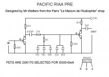
Pacific RIAA Pre - 24V Version
==============================
o-----------------------------------o------------+24V
| |
R2 R6
| |
| D---o---C7---o
D---o---C1--R3--o--------o------o---G OUT
o---o---G | | | S---o o
IN | S---o R4 | R5 | |
o | | | | | | |
| | | o--o--o o--o--o | | |
| R1 | | | | | | | | |
| | | C2 C3 C4 C5 C6 | | |
| | | | | | | | | | |
o---o-------o--------o--o--o--o-----o---o-------o--------o--- 0V
R1 = 100k C1 = 0.47 micro
R2 = 2.4k C2 = 15 nano (ideal C2 + C+ +C4 = 99.3 nF)
R3 = 27k C3 = 15 nano well my copy says 100nF
R4 = 3k C4 = 68 nano
R5 = 100k C5 = 22 nano here its 30nF total
R6 = 2.4k C6 = 6.8 nano
C7 = 2.2 micro
We build the Pre using both the Fet Pre Pre and the Pacific. PSU is 3 X PP3
NIMH Recharables. The Pre Pre get's it's PSU via a dropper resistor and a
2,200uF Decoupling Cap (Black Gate or similar) so that 12V are supplied to
the Pre-Pre.
Later Thorsten
______________________________________________________
"
formating is probably schmucked so- there is txt file
Attachments
I have no idea why you find this surprising???? Please elaborate on that. I was surprised by the sound of a simple circuit like that, but I dont think that is what you are aiming at?? What is your (ahem) aim??I find this one of the most surprising threads for a while.
Steen

I have been thinking about the batteries and the batteries used for RC cars would be perfect. They are built of 1.2 V cells strapped together to make whatever voltage necessary. In this case you can make a 16.8 V battery by simply strapping 14 cells together. They can be had as low as 1400 mAh to as high as 4200 mAh. Maybe a bit of overkill, but it hits the optimum voltage and they are readily available. Pick up a simple 18 volt DC wall transformer and you have a charger.
Dave M
Dave M

Manu said:Sorry, but Choky, the longer I'am starring at this picture the more I feel the deep humanity in your eyes.
Manu (OTs master)
Excactly, those eyes are hypnotizing
Steen
steenoe said:Twitchie: Draw up a schematic of how you connected things and post it
Steen
Thanks Steen, I think I just needed some good luck from you - I redid the layout from scratch (protoboard) and also found I forgot to add the ground drain on the pot - now it is working much better from DAC output to F4, but there's still some distortion (I swapped out 2.2K V+ rail resistor to 1K so I now measure approx 7.8-7.9V across jfet D-S pins (18.5V rail voltage).
It's 'working' now - should I adjust Rs? Any other measurements I should be taking?
V+ across 1K resistor (2.2K originally) - measures 6.58V
across JFET D-S - measures 8.01V
across Rs - measures approximately 67mV
here are some pictures:
http://www.flickr.com/photos/stephentom/544305020/
An externally hosted image should be here but it was not working when we last tested it.
Thanks again
Stephen
Twitchie, try to revert back to Mr. Pass's schematic!! Thats what I did and everything worked out fine!! You can't just swap out a 2,2K resistor with a 1K!!! As far as I remember , the Drain to Source voltage was around 5V's.... I havent got time for more measurements today
Steen
Steen
Manu said:Steen, forgive me master, how did you manage to get 35V out of 2 9V battery?
manu
silly question!
he connected them twice!
- Home
- Amplifiers
- Pass Labs
- Jfet BOZ