For changing inputs , If you know better option kindly guide.
give me a day I will post here for you.
Hello guys,
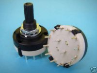
I am looking for rotary potentiometer type switches for audio Source Selection, Dont know proper technical Name, Please share any Knowledge regarding it.
Also If anybody has Relay based pcb diagaram for source selection.
this one i bought at bangalore for 50 Rs.
Attachments
this one i bought at bangalore for 50 Rs.
Any more details about connections , Technical name and where it could be available in Mumbai
Thank you
to viki 2
its name is two pole 'x' way rotary switch.where x is the no of ways.That means you can select many (upto x) stereo inputs with this single switch.Dont know about the availibility in Mumbai.Connections are easy both points present at inside will go to amp input and points at outer border are for inputs.chek continuty with multimeter,you will know youself.
its name is two pole 'x' way rotary switch.where x is the no of ways.That means you can select many (upto x) stereo inputs with this single switch.Dont know about the availibility in Mumbai.Connections are easy both points present at inside will go to amp input and points at outer border are for inputs.chek continuty with multimeter,you will know youself.
to viki 2
its name is two pole 'x' way rotary switch.where x is the no of ways.That means you can select many (upto x) stereo inputs with this single switch.Dont know about the availibility in Mumbai.Connections are easy both points present at inside will go to amp input and points at outer border are for inputs.chek continuty with multimeter,you will know youself.
Do you have pcb for relay based Input which will work with this Rotary Switch
thanks sangram, can you give more details
Basically you use the switch to power a pair of relays for each channel.
SPDT relays are easily available, cheap (around 20/ each) and work very well. DPDT relays are more economical, but there is danger of L/R crosstalk degradation.
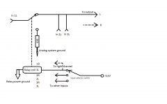
The pole of the relay switches the input between the signal input of the amp (T1) and ground (T2). The grounding of the input ensures that crosstalk between inputs is eliminated totally. You can use a low value resistor (100 ohm) on the ground leg to help the output device of the preceding stage short-circuiting (though in practical terms this is not a problem). All input throws and all ground throws can be connected to each other.
The actual switch is only used to turn power on to the relays as required. Two relays per switch position.
Clear as mud?
")
Very very ClearBasically you use the switch to power a pair of relays for each channel.
SPDT relays are easily available, cheap (around 20/ each) and work very well. DPDT relays are more economical, but there is danger of L/R crosstalk degradation.
The pole of the relay switches the input between the signal input of the amp (T1) and ground (T2). The grounding of the input ensures that crosstalk between inputs is eliminated totally. You can use a low value resistor (100 ohm) on the ground leg to help the output device of the preceding stage short-circuiting (though in practical terms this is not a problem). All input throws and all ground throws can be connected to each other.
The actual switch is only used to turn power on to the relays as required. Two relays per switch position.
Clear as mud?
Still I Request if you can make simple drawing Showing Connections from Relay to Switch, Also as there are many types of spdt relays which ones to look for,do you have image of any such relay showing pin position and top markings.
And for rotary Switch I suppose any Rotary switch which is 1 pole and x no of ways will work.
Thank You.
Yes, any switch will work.
Mac doesn't allow me to draw anything, so can't post one here, but you can look at this: Relay based Attenuators and Input Selectors
for an idea of the wiring. This particular one uses the relay to switch the signal into the relay pole, my circuits usually connect the input to the pole so I can switch the unused inputs to ground.
The relay coils are to be connected to a switch instead of the logic output, otherwise it's exactly the same. I use much smaller resistors to ground to be able to minimise any crosstalk.
Unfortunately about the relay you are correct and the wiring of the relay will depend on the relay you buy. There will be 5 contacts, and following is the combination you should get between two sets:
Fully open: NO
Fully shorted: NC
(these two will share one prong, which is where the incoming signal will connect)
Small resistance ~100 ohms: Coil.
Last edited:
Please explain your logic?
A preamplifier will be fine looking into a 100 ohm load. With the possible exception of some tube amplifiers.
Obviously you have not read the text, which on the previous page reads thusly:
The operative word being 'can'. One is free to float the NC input but deal with the potential of crosstalk given the very small space within a relay and potentially high voltages (some preamps will do about 4V output).
I have however noticed that if you leave the input floating there is a lot of crosstalk between inputs and it degrades system performance.
Finally, I have implemented exactly this a practical preamp that is gushed over by its owner and everyone else who has heard it, classifying at the most transparent preamp they have ever heard. It partners a $2500 speaker, $2500 CD Player and a $3000 amplifier, and none of his equipment have any problems feeding the load for the few seconds/minutes that they are kept close to ground. Some preamp and output stages (see the Ivy that accompanies the Buffalo DAC) actually keeps the LM4562 output shorted to ground with nothing more than its output resistor (22ohm, IIRC) between the output pin and ground.
Faulty preceding stages will have lots of issues, but then the problem is not in this circuit.
I would like your explanantion of the word 'disaster', after you crunch some numbers to figure out why a preamplifier of output impedance of 50 ohms or less will have problems feeding a 100 ohm load. Once you do the math, it works out fine.
A preamplifier will be fine looking into a 100 ohm load. With the possible exception of some tube amplifiers.
Obviously you have not read the text, which on the previous page reads thusly:
The pole of the relay switches the input between the signal input of the amp (T1) and ground (T2). The grounding of the input ensures that crosstalk between inputs is eliminated totally. You can use a low value resistor (100 ohm) on the ground leg to help the output device of the preceding stage short-circuiting (though in practical terms this is not a problem). All input throws and all ground throws can be connected to each other.
The operative word being 'can'. One is free to float the NC input but deal with the potential of crosstalk given the very small space within a relay and potentially high voltages (some preamps will do about 4V output).
I have however noticed that if you leave the input floating there is a lot of crosstalk between inputs and it degrades system performance.
Finally, I have implemented exactly this a practical preamp that is gushed over by its owner and everyone else who has heard it, classifying at the most transparent preamp they have ever heard. It partners a $2500 speaker, $2500 CD Player and a $3000 amplifier, and none of his equipment have any problems feeding the load for the few seconds/minutes that they are kept close to ground. Some preamp and output stages (see the Ivy that accompanies the Buffalo DAC) actually keeps the LM4562 output shorted to ground with nothing more than its output resistor (22ohm, IIRC) between the output pin and ground.
Faulty preceding stages will have lots of issues, but then the problem is not in this circuit.
I would like your explanantion of the word 'disaster', after you crunch some numbers to figure out why a preamplifier of output impedance of 50 ohms or less will have problems feeding a 100 ohm load. Once you do the math, it works out fine.
Can anybody kindly tell me where I can find a PCB maker in Kolkata? Thanks.
You are asking for a PCB maker?!!!
Seriously, though - on hifivision web site, diy group buy boards from PCBPower have been excellent.
E-mail i.d. - sales@pcbpower.com / service@pcbpower.com / powersupport@pcbpower.com
Contact No. - +91 9662059093 / 9558800479 / 9724316136
Last edited:
You are asking for a PCB maker?!!!
Seriously, though - on hifivision web site, diy group buy boards from PCBPower have been excellent.
E-mail i.d. - sales@pcbpower.com / service@pcbpower.com / powersupport@pcbpower.com
Contact No. - +91 9662059093 / 9558800479 / 9724316136
did you ever procure pcbs from PCBPower? can you pls tell us about its costing.
did you ever procure pcbs from PCBPower? can you pls tell us about its costing.
The recent group buys on hifivision have all been from PCBpower.
Their web site allows you to upload a gerber and get an instant online quote. It will
depend on how many you order etc.
I was not the organizer of the the group buy, so can't comment on costing, but
the group buy boards were of very good quality and the end cost was very
reasonable.
- Status
- This old topic is closed. If you want to reopen this topic, contact a moderator using the "Report Post" button.
- Home
- Design & Build
- Parts
- [INDIA] Chassis, knobs, PCB makers