gnd return R,L modeling doesn't change conclusions, the "one sided model" is the universal way the lumped approximation is shown in the literature
I think that as a series circuit you will have a hard time finding practical difference from modeling both wire's R,L
for a real cable model accuracy improvement, in my linked post I mention that skin/proximity effect could be modeled with added mutual L, steering high frequency current to some parallel R branches, "concentrating" the current, increasing apparent resistance as the other R paths are starved
Hi,
I modelled quickly - so could be mistaken the lumped element and distributed element of a cable - from Hifi News - a UK publication.
I assumed 3metres - stated parameters in Hifi News are 0.36uH/m, 4.6mOhms/metre, 295pF/m.
I ran the lumped element into 8ohms resistance, and distributed element also into 8ohms.
B2Spice allow you to implement the graph as a formula.
For the lumped element i used the vdB probe - which is always taken to 0volts.
For the distributed element i used dB[magnitude(voltage across 8ohms)] which has slightly different results.
Lumped element rolls off at 18dB/octave
Distributed element rolls off at 12dB/octave.
The lumped element as a clean roll off, where as the distributed element has two resonant peaks before rolling off - both simulated to 100MHz.
So - i may have my simulation wrong as it was completed is haste, but i do believe that lumped element is different to distributed element.
Regards,
Shadders.
I assumed 3metres - stated parameters in Hifi News are 0.36uH/m, 4.6mOhms/metre, 295pF/m.
EWB say -1dB @ 23kHz
I think it's fair to say we get a similar shaped curves for the two models. Out of interest, what did you get for -1dB point?
Last edited:
i do believe that lumped element is different to distributed element.
Apart from the curves being different only beyond audibility (gentle roll-off v "spikey" looking response), I get the -1dB (which I think I read as being the all important cut-off point) to be the same for lumped and distributed simulations.
I'm no expert by any means so I'm not all that sure I'm doing anything useful or that relates to the real world. I hope to actually compare the EWB sims with real-world measurements at some point.
EWB say -1dB @ 23kHz
I think it's fair to say we get a similar shaped curves for the two models. Out of interest, what did you get for -1dB point?
Hi,
At the -1dB point, i obtain 600kHz for the distributed response and 700kHz approx for the lumped response.
I think the 1dB at 23kHz may mean you may be using too many elements - or the cable length is quite long ?
Regards,
Shadders.
Hi,
I assumed 3metres - stated parameters in Hifi News are 0.36uH/m, 4.6mOhms/metre, 295pF/m.
0.36uH/m seems a bit low
295pF/m seems a bit high
Do you know what gauge and spacing were they using?
Apart from the curves being different only beyond audibility (gentle roll-off v "spikey" looking response), I get the -1dB (which I think I read as being the all important cut-off point) to be the same for lumped and distributed simulations.
I'm no expert by any means so I'm not all that sure I'm doing anything useful or that relates to the real world. I hope to actually compare the EWB sims with real-world measurements at some point.
Hi,
I may be wrong - not sure regarding the simulation of lumped and how i measured the signal of interest - across the 8ohm load.
As you have stated the differences are at the higher frequencies beyond the hearing capability of people.
A frequency response will only indicate the steady state levels at the speaker terminals - but a transient response may be more revealing.
I don't have golden ears - so i would not know if there are differences between cables - but too many people report that there is - this is in publications, not just forums - so scientific analysis must be pursued to resolve where the percieved differences occur.
Regards,
Shadders.
0.36uH/m seems a bit low
295pF/m seems a bit high
Do you know what gauge and spacing were they using?
Hi,
This was a Highly Commended cable in Hifi News - states as above the specifications - other have lower 105pF, down to 30pF and up to 925pF.
So i used one that was recommended and had high capacitance and slightly below average inductance.
Regards,
Shadders.
multiple RLC sections are still called lumped element approximations - Spice also has a "continuous" transmission line model
some like to use just a single RLC section - may often be good enough for audio - but multi section RLC lumped TL can approach the continuous model in accuracy at increasingly higher frequency as the number of sections/cable length increase
and, as usual, audio frequency "transients" don't stress the accuracy of even single section RLC cable models for domestic <10m lengths compared to the continuous TL models - as long as both are ignoring skin/proximity effect
About ten years ago, Cyril Bateman did some cable modeling and testing. It quickly got complicated.
http://www.waynekirkwood.com/Images/pdf/Cyril_Bateman/Bateman_Speaker_Amp_Interaction.pdf
http://www.waynekirkwood.com/Images/pdf/Cyril_Bateman/Bateman_Measuring_Cables.pdf
http://www.waynekirkwood.com/Images/pdf/Cyril_Bateman/Bateman_Speaker_Amp_Interaction.pdf
http://www.waynekirkwood.com/Images/pdf/Cyril_Bateman/Bateman_Measuring_Cables.pdf
multiple RLC sections are still called lumped element approximations - Spice also has a "continuous" transmission line model
some like to use just a single RLC section - may often be good enough for audio - but multi section RLC lumped TL can approach the continuous model in accuracy at increasingly higher frequency as the number of sections/cable length increase
and, as usual, audio frequency "transients" don't stress the accuracy of even single section RLC cable models for domestic <10m lengths compared to the continuous TL models - as long as both are ignoring skin/proximity effect
Hi,
From memory, the transmission line for Spice is based on a single conductor with the return path a perfect conductor - similar to a strip line analysis.
I think you can simulate a balanced transmission line by connecting two spice transmission lines together - about the ground plane conductor - or 0volts line with capacitances and inductors sized accordingly.
Regards,
Shadders
Continuous models and lumped are identical as long as each lump is less the 10% of the electrical wavelength. It is unusual for either model to take into account changes of resistance due to skin depth or capacitance with dielectric constant over frequency.
Hi,
My original statement was that the speaker cable should be modelled as a balanced network - as stated by others distributed lumped elements can approximate a continuous model as the number of elements increase.
Also, as others have stated, for audio frequencies the lumped element approach and generally the single lumped elements are sufficient. What cannot be shown is why some people hear differences for cables that have similar electrical characteristics - differences have no impact over the audio spectrum.
Regards,
Shadders.
Last edited:
Hi,
At the -1dB point, i obtain 600kHz for the distributed response and 700kHz approx for the lumped response.
I think the 1dB at 23kHz may mean you may be using too many elements - or the cable length is quite long ?
Regards,
Shadders.
I used the vales of 0.36uH/m, 4.6mOhms/metre, 295pF/m then multiplied each by 3 for a 3m cable which gave -1dB @ 28kHz (not 23k, my bad). I used a single component for R, C and L while Z(speaker)=4ohms.
I guess L should be even lower. In fact, halving L gave -1dB @ 64kHz. An improvement.
I used the vales of 0.36uH/m, 4.6mOhms/metre, 295pF/m then multiplied each by 3 for a 3m cable which gave -1dB @ 28kHz (not 23k, my bad). I used a single component for R, C and L while Z(speaker)=4ohms.
I guess L should be even lower. In fact, halving L gave -1dB @ 64kHz. An improvement.
Actually, scrap the above. Maybe my EWB is playing up (it does sometimes). I'm now getting the same results shadders got for the "Hifi News cable".
For a 3m length i.e. multiply 0.36uH, 4.6mOhms and 295pF each by 3, I'm getting 700kHz into 8ohms and roughly 350kHz into 4ohms.
0.36uH/m seems a bit low
295pF/m seems a bit high
Do you know what gauge and spacing were they using?
Low L is good though? Do you mean L seems low compared to inductances of typically cables on the market or too low to be any good?
I have noticed most commercial cables have L higher than 0.36uH/m and my sims so far have shown them to be very poor cables in terms of high frequency performance: Nordost Vahalla as an case in point with L=33uH/m!
Of course, I take the points made about hearing differences that aint seen in sims or on scopes. I'm trying to get the first-order stuff right before I build a set of cables. Btw, I fancy building copper foil cables wrapped in cotton.
Cheers.
Last edited:
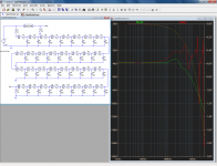
In my first sim, I made a factor of 10 error in the sections of the lumped line.
It doesn't change the gist of my argument though: here is the comparison, and with the resistance also spread between the lumps.
The two transfer functions begin to diverge as early as 20KHz, to reach ~1dB at 100KHz (for 10m sections).
The phase/time aspect is more accurately modelled though: this means that such artificial lines are suitable as delay lines, but not as cable simulators.
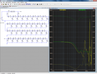
There are much better topologies for that, departing completely from the method consisting to attempt to duplicate the elementary L/C cells (which have no actual existence, since they are infinitesimal).
The impedance plots are also seriously divergent above the corner frequency:
It doesn't change the gist of my argument though: here is the comparison, and with the resistance also spread between the lumps.
The two transfer functions begin to diverge as early as 20KHz, to reach ~1dB at 100KHz (for 10m sections).
The phase/time aspect is more accurately modelled though: this means that such artificial lines are suitable as delay lines, but not as cable simulators.
There are much better topologies for that, departing completely from the method consisting to attempt to duplicate the elementary L/C cells (which have no actual existence, since they are infinitesimal).
The impedance plots are also seriously divergent above the corner frequency:
Attachments
Low L is good though? Do you mean L seems low compared to inductances of typically cables on the market or too low to be any good?
I have noticed most commercial cables have L higher than 0.36uH/m and my sims so far have shown them to be very poor cables in terms of high frequency performance: Nordost Vahalla as an case in point with L=33uH/m!
Of course, I take the points made about hearing differences that aint seen in sims or on scopes. I'm trying to get the first-order stuff right before I build a set of cables. Btw, I fancy building copper foil cables wrapped in cotton.
Cheers.
Hi,
The inductance was as printed - th other cables had similar - some higher and some lower, but these values seem typical.
Regards,
Shadders.
In my view there is no point whatsoever in building a cable. If you can hear a difference between it and an appropriate normal commercial cable then that just means your DIY cable is particularly bad. (Bad at one or more of: high C, high L, high R, high RF pickup, high microphony).deanxxx said:I'm trying to get the first-order stuff right before I build a set of cables. Btw, I fancy building copper foil cables wrapped in cotton.
If you want to DIY components (a cable is a component) then do this for those which could have a bigger effect on the sound, such as resistors, caps or transformers (or speakers?). You will find that in almost all cases it is easy to change the sound, but much harder to actually improve it. Reputable component/cable manufacturers do know what they are doing.
The aim of your current investigation should be to demonstrate to your own satisfaction that cables are not that important, provided a few electrical parameters are correct.
In my view there is no point whatsoever in building a cable. If you can hear a difference between it and an appropriate normal commercial cable then that just means your DIY cable is particularly bad. (Bad at one or more of: high C, high L, high R, high RF pickup, high microphony).
If you want to DIY components (a cable is a component) then do this for those which could have a bigger effect on the sound, such as resistors, caps or transformers (or speakers?). You will find that in almost all cases it is easy to change the sound, but much harder to actually improve it. Reputable component/cable manufacturers do know what they are doing.
The aim of your current investigation should be to demonstrate to your own satisfaction that cables are not that important, provided a few electrical parameters are correct.
You make a good point.
I think I have learned about those parameters.
Still, it's interesting. I have plans to build a few speakers also, just for the hell of it I guess

Cheers all.
Hi,
The inductance was as printed - th other cables had similar - some higher and some lower, but these values seem typical.
Regards,
Shadders.
I'd be happy to try that cable. Cheers for your input Shadders.
- Status
- This old topic is closed. If you want to reopen this topic, contact a moderator using the "Report Post" button.
- Home
- Design & Build
- Parts
- Modelling Audio Cables