Active subwoofer and satellite filter boards
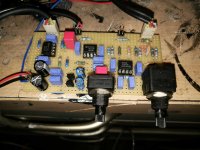
Prototype for an active crossover. Will be used in a pa subwoofer with big class d amplifier.
Features are:
Balanced in
Adjustable lowpass 50-250Hz
Volume control sub channel
Phase invert switch
Balanced out sat channel fixed level and highpass 120Hz.
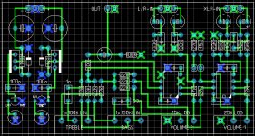
I will also make a board for active satellite with following features:
Balanced in with mic/line switch and volume control
Unbalanced line in with volume control
Tone control bass/treble
Subwoofer amplifier will be something like this:
https://m.aliexpress.com/s/item/325...ubject=32562266578&shortkey=ZJZRv6V3#autostay
Prototype for an active crossover. Will be used in a pa subwoofer with big class d amplifier.
Features are:
Balanced in
Adjustable lowpass 50-250Hz
Volume control sub channel
Phase invert switch
Balanced out sat channel fixed level and highpass 120Hz.
I will also make a board for active satellite with following features:
Balanced in with mic/line switch and volume control
Unbalanced line in with volume control
Tone control bass/treble
Subwoofer amplifier will be something like this:
https://m.aliexpress.com/s/item/325...ubject=32562266578&shortkey=ZJZRv6V3#autostay
Attachments
Last edited:
Hi, are you planning to post a schematic?
This is the current schematic.
Attachments
Last edited:
looks like you are adopting a B2 (Butterworth 2pole) filter.
Bass channel: change the 220nF to 200nF to get the correct roll off.
Mid/Treble channel: why an extra gain of 3.2times (+10.1dB)?
You have differential interference filtering, but no common mode filtering.
Add a couple of pF NPO ceramic from pins 2&3 to enclosure at the XLR socket. You can increase the effectiveness of these filters by preceding them with 100r or similar.
I don't see any advantage in using the 3k3 impedance reducer at the input.
Note that the two GND symbols at the input are Pin1 and go to enclosure.
All the later GND symbols are audio ground and these do not go to the enclosure.
Except the balanced output which should have another Pin1 connection to the enclosure.
This balanced output shows GND to - out. This is wrong !
I recommend you look at adopting AC coupling either at your balanced outputs, or at your balanced inputs.
Last edited:
Why not to use Linkwitz-Riley filters:
http://www.linkwitzlab.com/filters.htm
http://www.rane.com/note160.html
http://www.diyaudio.com/forums/analog-line-level/271802-lr4-smd-filter-project.html
Maybe you better to take relatively cheap db technologies DBX223 crossover or Behringer CX2310?
http://www.linkwitzlab.com/filters.htm
http://www.rane.com/note160.html
http://www.diyaudio.com/forums/analog-line-level/271802-lr4-smd-filter-project.html
Maybe you better to take relatively cheap db technologies DBX223 crossover or Behringer CX2310?
Last edited:
looks like you are adopting a B2 (Butterworth 2pole) filter.
Bass channel: change the 220nF to 200nF to get the correct roll off.
Mid/Treble channel: why an extra gain of 3.2times (+10.1dB)?
You have differential interference filtering, but no common mode filtering.
Add a couple of pF NPO ceramic from pins 2&3 to enclosure at the XLR socket. You can increase the effectiveness of these filters by preceding them with 100r or similar.
I don't see any advantage in using the 3k3 impedance reducer at the input.
Note that the two GND symbols at the input are Pin1 and go to enclosure.
All the later GND symbols are audio ground and these do not go to the enclosure.
Except the balanced output which should have another Pin1 connection to the enclosure.
This balanced output shows GND to - out. This is wrong !
I recommend you look at adopting AC coupling either at your balanced outputs, or at your balanced inputs.
Thanks for your reply.
I have made some changes to the schematics.
I have added capacitors on all inputs and removed the 3K3 resistor.
The circuit is noise free, so I'm not sure if the extra filtering on the input is needed.
Changed the 220n to 2x100n for the lowpass filter.
Changed the 22K resistors on the mid/high balanced input to 10K for less gain,
Maybe you better to take relatively cheap db technologies DBX223 crossover or Behringer CX2310?
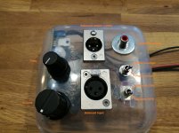
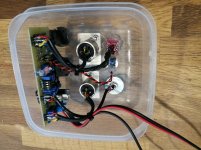
I want to build active speakers with this filter inside the speaker cabinet.
which speaker cabinet?
Inside the satellites (two), or inside the bass only (one or two)?
OR
fit the relative filter to the amplifier driving that speaker.
2 subs both with the filterboard for bass channel and an amplifier inside
2 tops both with the filterboard for mid/high channel and an amplifier inside
So all active stereo 2-way
You don't build a crossover.
You build a filter to suit each active speaker.
You are right, they are separate filter boards, but simmed together.
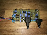
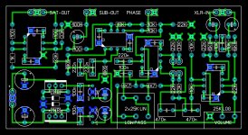
Today I will test version 2 of the subwoofer board.
I added a selectable highpass (currently resistors are set for 25Hz and 40Hz, but can be changed according needs)
Also I added 2 transistors in the powersupply circuit so the board can run directly from amplifier voltage rails up to 80V (small clipon heatsinks needed). Now testing with +40V/-40V rail voltages, highest as my lab powersupply will go")
Trying to fit the circuits on 5cmx10cm boards as this size is very cheap in china for dual sided PCB.
I added a selectable highpass (currently resistors are set for 25Hz and 40Hz, but can be changed according needs)
Also I added 2 transistors in the powersupply circuit so the board can run directly from amplifier voltage rails up to 80V (small clipon heatsinks needed). Now testing with +40V/-40V rail voltages, highest as my lab powersupply will go
Trying to fit the circuits on 5cmx10cm boards as this size is very cheap in china for dual sided PCB.
Attachments
Last edited:
Why in the heck did you go fixed @ 120????
I have been looking for something similar but highpassed @ 120 means no mini line array use???
You can change the crossover frequency by changing 2 resistors.
You can change the crossover frequency by changing 2 resistors.
I see. Thanks!
I see. Thanks!
What highpass frequency would you like to have?
I can sim the correct values.
- Status
- This old topic is closed. If you want to reopen this topic, contact a moderator using the "Report Post" button.
- Home
- Live Sound
- PA Systems
- Active subwoofer and satellite crossover