Thanks for the link. You know it was always in the back of my mind about inductor proximity with each other but I never explored it fully. I suppose I thought air cored inductors would have a much more sparse magnetic field than iron cored ones and thus talk less to each other. I am now about to pull the xovers apart and re orientate the inductors as I may well have inadvertently misaligned them (I should have known better, kicking myself now). Looks like a definite redo of the artwork. Thanks for the info.
My Elsinore's are alive!
Fellow builders,
I brought in my Elsinore's and installed them on Saturday afternoon. Yes, 90 lbs is about right, but I had help.
Although they are of course not broken in I spent several hours listening and enjoyed what I heard very much. This is the seventh set of DIY speakers I built and they are clearly the best, by wide margin.
Thanks to Joe for sharing his design and proving guidance, and to all of you for help, support, wave guides, experience and on and on.
Francois
Elsinore Xover rejigged.
I've now rejigged the inductors in my xovers to satisfy the data given by Troels Gravesen. (as best I can given the constraints of my pcb). Many thanks to JdkJake for the link. It'll do for now but I'll definitely have to redo the artwork to satisfy myself. At first listen my impression is better performance at high listening levels which I guess would make sense as the cross coupling would surely be worse at higher levels as the induced fields between the inductors would be greater. My nice neat pcb is looking a bit messy now however. It's another good reason not to mount the xovers inside the cabinets.
I've now rejigged the inductors in my xovers to satisfy the data given by Troels Gravesen. (as best I can given the constraints of my pcb). Many thanks to JdkJake for the link. It'll do for now but I'll definitely have to redo the artwork to satisfy myself. At first listen my impression is better performance at high listening levels which I guess would make sense as the cross coupling would surely be worse at higher levels as the induced fields between the inductors would be greater. My nice neat pcb is looking a bit messy now however. It's another good reason not to mount the xovers inside the cabinets.
Attachments
I've now rejigged the inductors in my xovers to satisfy the data given by Troels Gravesen. (as best I can given the constraints of my pcb). Many thanks to JdkJake for the link. It'll do for now but I'll definitely have to redo the artwork to satisfy myself. At first listen my impression is better performance at high listening levels which I guess would make sense as the cross coupling would surely be worse at higher levels as the induced fields between the inductors would be greater. My nice neat pcb is looking a bit messy now however. It's another good reason not to mount the xovers inside the cabinets.
Boy, that did not take long to reconfigure. Very handy and flexible board you have there to be able to make such dramatic changes so quickly.
Put together the main wiring harness that ties into the speakON connector. The speakON spades fit one side of the peerless drivers perfectly (the positive side). The negative, not so much. A bit of "modification" and rework is needed to get a good mechanical grip on the small spade negative side of the drivers (same with the tweeter lugs) using the neutrik spades. In hind sight, I should have gotten the proper spade for those lugs. But, the neutrik spades were already installed and solder into the harness and I was able to get them to work just fine. It would be nice if this was a standard across all connectors. Perhaps it is, but, I was unaware of it if it was.
In any case, installed the drivers, screwed them down tight and also installed the neutrik jack. So far, I am happy with the neutrik system. Very clean and neat.
Jake, great harnesses and nice double heatshrinking.
The zip tying of the cable was a nice touch too.
Have you thought about soldering the cable directly to the speaker terminal?
I find it gives a better connection and better sound.
Interested in building a pair of these to replace my B&W 603 floorstanders.
Has anyone had experience using an electronic crossover with them?
Is there any reason why an active crossover would be a bad choice over the passive?
Thanks
Any responses to this post?
Any info is appreciated.
When I was researching my build I saw some posts that indicated that someone was trying an electronic crossover with the Elsinores. He was never satisfied with the results. The crossover is such an integral part of the speakers, such as 6db per octave rolloffs, phasing etc. that I would go with the passive. The Bolserst mod uses a notch filter on the "mids" that you wouldn't be able to do with active.
I too was having trouble with interactions between the inductors and put a 10" post on the crossover board and mounted the iron core inductor on top of it. Not pretty but effective. Got the inductors away from each other and didn't increase the footprint of the crossover board.
Has anyone else tried the Bolserst crossover mods besides Joel? Would be interested in your comments.
I directly soldered all my connections as I don't particularly trust crimp connections unless they are also soldered. As far as active xover for the Elsinore's after looking at how much design and testing work Joe Ras put into the passive networks and the fact that they are mostly 1st order I can't see how an active one can reproduce let alone improve the results. They would cease to be Elsinore's!
I'm very interested to hear what you think of them once you fire yours up. You must be so close you can taste it!Boy, that did not take long to reconfigure. Very handy and flexible board you have there to be able to make such dramatic changes so quickly.
Jake, great harnesses and nice double heatshrinking.
The zip tying of the cable was a nice touch too.
Have you thought about soldering the cable directly to the speaker terminal?
I find it gives a better connection and better sound.
Thanks.
I did think about direct soldering the cable and still might. For the time being at least, I wanted to have the flexibility of easily changing out drivers until everything has been verified operational and settled in.
I'm very interested to hear what you think of them once you fire yours up. You must be so close you can taste it!
Yeah, getting pretty excited. I hope to build up the cross overs this weekend. Just need to clear my plate first at the day job. A most demanding presence right now.
But, it pays for the toys, so, it is hard to complain.
Beautiful job on the cabinets jdkJake! They look gorgeous and professional.
A few questions, will these be in a dedicated 2-channel music only system or HT? What equipment will be driving these? Approx square footage of the listening room?
Thanks for the kind words.
These will move into my main listening area. They will serve double duty in that space. Once the Hamlet crossovers are finalized, I will be building matched center and rear channels. Equipment will vary as I built these explicitly to experiment with various amplifier topologies. My room size is a bit hard to characterize. While the room is of medium size, it opens up into the rest of the house which makes it very difficult to adequately size the true total square footage. Hence my desire for a "big" design with broad dynamics potential.
We shall see how they do soon.
DId you notice a significant difference in performance once the inductors were separated?When I was researching my build I saw some posts that indicated that someone was trying an electronic crossover with the Elsinores. He was never satisfied with the results. The crossover is such an integral part of the speakers, such as 6db per octave rolloffs, phasing etc. that I would go with the passive. The Bolserst mod uses a notch filter on the "mids" that you wouldn't be able to do with active.
I too was having trouble with interactions between the inductors and put a 10" post on the crossover board and mounted the iron core inductor on top of it. Not pretty but effective. Got the inductors away from each other and didn't increase the footprint of the crossover board.
Has anyone else tried the Bolserst crossover mods besides Joel? Would be interested in your comments.
I separated the inductors after Bolserst did his measuremnts and indicated that there might be some interactions. At the same time I moved the iron core I did the mods that he suggested. Hence I can't say how much of the change was attributed to the movement of the intuctor. However, the overall sound became much more focused and tighter after the mods.
I've now rejigged the inductors in my xovers to satisfy the data given by Troels Gravesen. (as best I can given the constraints of my pcb). Many thanks to JdkJake for the link. It'll do for now but I'll definitely have to redo the artwork to satisfy myself. At first listen my impression is better performance at high listening levels which I guess would make sense as the cross coupling would surely be worse at higher levels as the induced fields between the inductors would be greater.
Hello irext,
Determining placement and orientation for minimum coupling between coils by ear:
Rules of thumb to minimize coupling basically boil down to 1) distance is good, 2) if you can’t get distance, proper axis orientation can help.
Here is another useful link on the subject with measurement:
Inductor Coil Crosstalk Basics — Reviews and News from Audioholics
For those without oscilloscopes or LCR meters, determining levels of goodness for these rules of thumb and any other arrangement can be done in a rather simple manner. Tools needed are a pair of headphones, amplifier, 4 ohm 20W resistor, and a signal generator or test disk. Hook the leads of one inductor to your headphones. Hook the leads of the second inductor to the amplifier with the 4 ohm resistor in series with one of the connecting wires. Play a 1kHz – 2kHz signal thru the amplifier. Usually < 10Watt is adequate to hear a strong tone in the headphones when the two coils are placed in close proximity to each other.
Listening to the amplitude of the tone, you can get a feel for how distance and orientation affects the coupling. You will find that at close distances minimizing the coupling thru axis orientation can be quite critical of angle adjustment.
Considerations for iron core inductors:
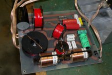
I noticed you had two 9mH iron core inductors hooked in series to get the required 18mH. However, when the iron cores of two inductors are positioned in-line and close together there is considerable mutual inductance generated thru coupling.
Attachment #1: Actual inductance measurements for two series connected 6mH inductors
(A) Where coupling is minimized by axis orientation, total inductance = 12mH
(B) Where mutual inductance is additive, total inductance = ~23mH
(C) Where mutual inductance is subtractive, total inductance = ~10mH
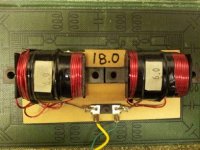
Case (B) can be used to your advantage when creating larger value inductors from two small ones. The gap between the cores can be adjusted to give a value anywhere between 2 to 4 times the individual inductances. For example, Attachment #2 shows an 18mH test inductor I build from the two 6mH inductors carefully spaced apart be MDF blocks.
So, depending on the orientation of your 9mH inductors I would estimate the total inductance is probably either ~23mH or ~16mH; not the 18mH you were going for. The good news is that this inductor is only used for impedance compensation "up-stream" of the woofer crossover and has fairly non-critical tuning. But, something to keep in mind if you ever use inductors like this for critical areas of a crossover.
Another thing to point out about case (C) is that the magnetic fields from the two inductors are bucking against each other. This results in a strong flux field shooting radially outward from the gap between the cores. So, positioning other inductors near this area is not a good idea. You can confirm this by listening to the tone from a coil placed in this area. Case (C) will produce considerable louder tones in the headphones than case (B). Attachment #3 is an attempt to graphically depict the behavior of the flux fields for cases (B) & (C).
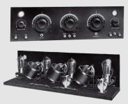
Old tricks rediscovered:
While playing around with coil placement, you may accidentally stumble on the fact that there is another orientation besides orthogonal axes that will minimize coupling between coils. If you start with two coils spaced slightly apart and oriented in the same direction and then rotate both of them at the same time in the same direction, you will find somewhere in the 50deg – 60deg range the coupling completely disappears. The exact “magic” angle depends on the coil diameter and length, and is pretty easy to find by ear with the technique described above. This behavior was patented by Hazeltine (US 1577421) in the early 1920s for use in cascaded RF amplifiers in early unshielded radios. See Attachment 4 & 5. The cool thing is that you can line up any number of similar sized/shaped coils at the same spacing and angle and there will be minimal coupling between any/all of them.
Attachments
As far as active xover for the Elsinore's after looking at how much design and testing work Joe Ras put into the passive networks and the fact that they are mostly 1st order I can't see how an active one can reproduce let alone improve the results. They would cease to be Elsinore's!
Thanks for that.
It looks like I will stay with the original passive crossover plan then.
Its a shame as I have two Rotel rb1080 power amps (was thinking of getting a third) but I can still bi-amp.
Maybe I'll even experiment with passive crossover for the mids and highs, and active for the mids and bass?
What are your thoughts?
My current crossover is a nakamichi ec100 two way with seperate power supply.
- Home
- Loudspeakers
- Multi-Way
- The "Elsinore Project" Thread