Hi Guys
Sorry if I have been somewhat incognito for a while. Lots of other distractions and I wear many hats - in fact amplifiers have been my focus of late as well as digital playback and upgrading Oppo players.
When the weather gets a little warmer, will get my head around the Hamlets.
Yes, the question is whether they will be 16 Ohm nominally (but actually 12 Ohm - which means by convention 0.707*Z cannot be rated as 16 as that comes out 11.3 minimum Z).
But if we go for 4 Ohm, then it will actually be 3 Ohm. Again the same convention applies and 4 Ohm Z is allowed a minimum of 2.83 Ohm.
If the latter, the voltage sensitivity will be close to Elsinores, but it will draw the twice the current - hence efficiency will be exactly half.
But if we go for 12/16 Ohm, then the voltage sensitivity will be low, but efficiency will still be the same as 3/4 Ohm.
Hence we can see that sensitivity and efficiency are not the same. Whichever way we go, they will have the same efficiency, but one will be -6dB lower sensitivity.
Which way to go? I am open to a consensus onion.
Cheers, Joe R.
Last edited:
Re Bolser mod
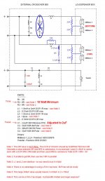
Re proposed Bolser mod, if they are to be tried, then this is the way I would implement them.
This will take a series of postings, so please bear with me. I won't respond to other postings till I completed them.
But personally I would prefer things as they are - for the time being.
Here is the Bolser changes - but not as I would see them, but do them differently in a number of respects and why.
Attachments
Last edited:
Let us take it one step at the time.
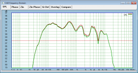
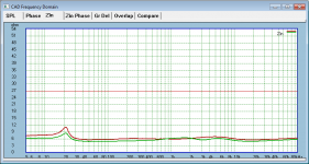
What effect will adding the 33R resistors across Voice Coils?
In fact very little difference in response. Take a look below, Red is without and Green is with.
Note this is 15 degrees OFF axis.
Note that there are two scales shown, my usual 5dB scale. The difference is easier when 1dB scale, but it looks uglier.
It won't sound brighter that for sure.
Attachments

Last edited:
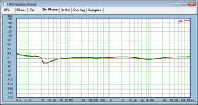
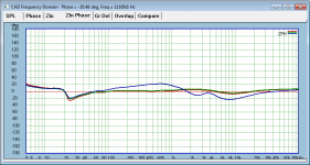
Now let's look what happen to the Z.
Other than it being lower, it still keeps it overall shape well.
Is some feels that is better, then OK by me.
Maybe the 1.8uF (which I use) for the Tweeter, its value could be increased slightly to correct the balance if you find it a little duller.
Other than it being lower, it still keeps it overall shape well.
Is some feels that is better, then OK by me.
Maybe the 1.8uF (which I use) for the Tweeter, its value could be increased slightly to correct the balance if you find it a little duller.
Attachments

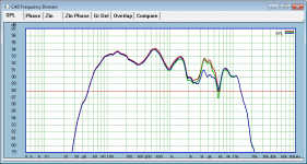
Let us now take a look at the electrical phase, and here I have some problems that I would like to see addressed.
Red is original, Green is parallel 33R resistors only, and Blue is the whole hog, caused by the 33R resistors, additional parallel resistor to choke and LCR plus omitting conjugate.
Red is original, Green is parallel 33R resistors only, and Blue is the whole hog, caused by the 33R resistors, additional parallel resistor to choke and LCR plus omitting conjugate.
Attachments
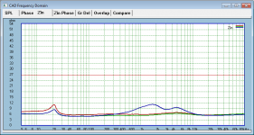
Clearly the conjugate is out of whack.
By changing the conjugate we can end up with the following.
Here Red is way back to the original and Green will be with the Bolser mod further modded. Basically retuning the conjugate:
By changing the conjugate we can end up with the following.
Here Red is way back to the original and Green will be with the Bolser mod further modded. Basically retuning the conjugate:
Attachments
Last edited:
OK, by now I may have caused some confusion. But it has to be understood that the Elsinore Mark 5 has certain aims that I feel needs to be achieved as close as possible to the ideal.
When we speak of what is ideal, then I admit we are talking about ideology.
Every loudspeaker designer worth his salt develops his ideology as it focusses the mind and gives him certain aims and targets.
I am no different.
So maybe some general thoughts behind my current ideology and its aims seems to be in order. They have of course evolved (a word I am not entirely comfortable with) and the Elsinore Mark 5 is basically where that has ended up and right now has not changed.
We all make assumptions, we all make value judgements, and then find ways to either maximise them or ways to deal with them.
So what are some of these with the current Elsinores?
Well, for a start, have you ever wondered why many people are so enamoured by full-range driver systems? Why others find electrostatics the way to go, and others go the ribbon (and not just for tweeters)?
And then we have multi-way speaker systems, and the above addicts look down upon those?
Is there something that links all these views, and explains to a large extent the preferences people have made and the camps they have decided upon?
All variations are imperfect.
But is there something about multi-way that makes them deficient to the others? Is there something they have found and really like and that they just feel multi-way is not up to scratch?
What could that be?
Multi-ways do indeed do some things well. They can be designed to go very loud, even very low distortion (in the conventional sense of the word) and wide bandwidth.
But is there something lacking that the others have a magic that multi-way does not?
Yes, I believe there is, and it comes down to the way they deal with current.
Power delivery we generally use is voltage.
Electrostatics are voltage devices. This is a matching interface.
Ribbons? They are current devices, but the current drawn by them is very linear and low phase over much of the most critical frequencies, from low mids to treble.
Full-range? Their Z and electrical phase is very predictable and there is no interference caused by a crossover, hence current from voltage devices (amplifiers) is also equally predictable and much less can go wrong. Much of their load above 200 hertz is positive (inductive) phase and benign load.
Negative (capacitive) phase angles are bad, not just for the amplifier, but can cause error patterns in the way the electrodynamic motor responds.
Now what about multi-way? Apart from a myriad of things that needs sorted, the question is: What does multi-way do the current from voltage sources/devices?
The ideal power delivery is current delivery - but very impractical and very difficult to grasp as it is not as intuitive in the way that voltage drive is. The point is that current sources can only produce current that has a zero phase angle. This is what electrodynamic drivers are compatible with. Voltage delivery can produce current of any electrical phase angle.
What determines the phase angle? The amplifier? No, the load does.
Hence, getting as close to possible to current drive, we need to control the load on the amplifier.
There are rules that determines when current behaves well and when it doesn't. When it does not, then the result is phase noise, yes, better known as jitter.
Avoid parallel networks across the driver, ones that changes Z and phase with changing frequency. A resistor in parallel is likely to be less destructive (or obstructive), as a constant R means it will have a flat phase angle.
Series components should be maximised, where parallel is bad, series is good.
I won't go into exact details here, but the Waveguide is totally crucial in this scheme of things.
If parallel networks are employed, the must not modify the response and they must be seen by the source (sender) and not the final load (receiver).
The Mark 5 is contrived to follow those rules.
The final result is not designed to sound like an electrostatic or a ribbon, but maybe a lot closer to full-range, but without the bandwidth limitations and lower distortion. And potentially much greater dynamic range.
The end results should be greater coherence, more relaxed, less cluttered soundfield and clear but not etched outlines of instruments, where the size of the instruments are not bloated. But one of the really amazing things is that it is able to, every now again, produce sounds that seems just to expand the size of the room, as if that sound could not be contained (or produced) in that room. It is apparent in some of the best film scores.
If you love speakers that image well, then the Elsinores will fit the bill and even exceed your expectations of what speakers are capable about.
May I also end on a final note:
This speaker is very VERY sensitive to speaker location within the room.
Get them well away from the rear wall as you can. Calculate the length of the room (the direction the speaker is firing), multiply by 3 and then divide by 10.
If that is 5 Metres, then the front of the Waveguide should be 1.5M, for 4M then 1.2M and 6M then 1.8M and so on. The amount of toe-in is not of import here, that is separately decided. The distance of the rear of the speaker is not important.
Place them as wide as possible while still getting a stable centre image, experiment with toe-in. The Bolser mod tolerate more to-in.
Oh dear... that was a lot.
Off to bed.
Cheers, Joe R.
Last edited:
The end response will end up as per Bolser, but with a flatter Z and to me even more important, a flatter electrical phase.
Hello Joe,
Thanks for posting your take on the minor crossover modification I proposed for tpate.
Since you brought up the topic of retuning the conjugate for flatter(but lower) impedance, I thought I would mention our experience with it here.
As you posted, the measured frequency response was the same with the conjugate removed, or retuned. Only the impedance seen by the amplifier changed.
Since tpate used a tube amplifier from time to time I thought the retuned conjugate would be the way to go. But, since I like experimenting, I proposed trying both with and without a retuned conjugate. Surprising both of us, both the solid state amp and the tube amp just sounded more effortless and clean with the conjugate removed. My guess is, that the easier load provided by the higher impedance outweighed possible advantages from linearizing impedance and phase.
Rather than post multiple options for modding the crossover, I decided just to post the one that wound up sounding the best in tpate's setup. That being said, if folks are trying out the mod, by all means try it with and without retuned conjugate. Depending on your electronics you may find you prefer the retuned conjugate in place.
Last edited:
I will take it in stages:
Stage 1:
Fit the 33R resistors, you will need eight in all.
That might be all you need to try. The tonal balance will be more gently downward and hence less bright. But since excess energy is what led us in this direction, maybe the less averaged out energy above 1Khz will go some way to assist. No more required.
You can proceed to Stage 2:
This is now getting more complex.
1. Add 10R in parallel with L2 0.33mH
2. Add LCR series network across (in parallel) with MidBass drivers, values are 0.47mH, 8R and 3.3uF.
This will change things away from the "currrent" rule that parallel elements cause phase noise, whereas series elements has a chance to reduce it.
Please note that we are violating the earlier rule - but we will analyse what affect that may have, so please read on.
I may add here that I have an alternative design of the Elsinores here in operation. Everything is much the same, except the 6.5" driver is is less problematic than the HDS driver and the 4KHz exxageration is much smaller. But it also has dramatically lower VC inductance, in fact the effective inductance is near a quarter, so much so that the 0.33mH used in the Elsinores needs to be 1.5mH - so in what manner does this influence what is done here in Stage 2?
Because with the Elsinores, much of the inductance is internal (6.5" driver), the LCR and its affect on potential phase noise (we are talking about effects that will eventually be modelled correctly and hence we are guided by general rules rather than absolutes) with the 10R in parallel with L2, hence the added LCR is seen more by the amplifier (voltage source) than it is by the driver itself - its self-inductance acts as a bufffer. The alternative driver with less inductance, it becomes more problematic - but thankfully not here.
So the likelihood is that significant added phase noise is lower with the Elsinore HDS driver than in the alternative driver I have used in the alternative design.
What is also clear is that the High-Pass to the Tweeter and its Waveguide is left untouched. The much lower value series capacitor means much higher reactance between the VC and the voltage source. So around 3-4KHz, the Tweeter tracks the current better, even if the source is voltage. This I suspect is where any potential phase noise would have the maximum audible and negative influence. And this remains in place and I would say inviolate.
In summary, Stage 2 may well have a benefit that comes at a minimum cost.
Stage 3.
If Stage 2 is tried, then in my view the conjugate made up of L5, R3 and C4 should be changed. The values are:
L5 - change from 0.18mH to 0.10mH (a reduction that can be achieved by simply reducing the winding on the existing choke, but you will need a bridge to measure it).
R3 - change from 8R to 10R
C4 - do not change, but keep at 33uF
Next: See below as they will show graphs before and after.
Last edited:
Welcome back, Joe!
It is great to have you back! Thanks for returning.
No, you are not causing confusion. You are helping to un-confuse.
I have been listening for the last four months to my Mk V's, which started life as Mk IV's. And I have been strangely disappointed! The speakers just disapear.
The Mk V's sound so "un-intrusive" and "un-remarkable" that I often forget to listen to loudspeakers and just enjoy the music! That is probably the best ecolades a speaker could have.
It's great that you would be looking at the Hamlet soon. I have my drivers ready to go. Bring it on!
Thanks again and best regards,
Francois
It's great that you would be looking at the Hamlet soon. I have my drivers ready to go. Bring it on!
I will try. Thanks for the encouraging words. You like my speakers? Then I like you.
")
Cheers, Joe
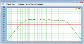
I wonder what results you,ll get for the port tunning using the mike and a low frequency sweep.
Probably something like this.
One is the left speaker and the other the right speaker. The calibrated mic is placed at the exit of each port. The audioTools FFT is set to average out pink noise for a couple of minutes (unweighted). I thought the pink noise worked a bit better than single/multiple sweeps. Certainly for establishing a consistent measure.
The configuration under test is with the standard 3 inch electrical coupling port extended by an additional 20mm. I first tried 10mm of extension and it did not take the tuning quite deep enough. The 20mm length might be a bit too much as I am calculating ~32Hz from the impedance measure. I am going to try out a 15mm extension and see how that measures.
Attachments

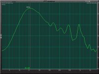
The calibrated mic is placed at the exit of each port.
For a nearfield measurement, that looks reasonable. The 500Hz/1KHz peaks are suppressed by the fact that the port is at the rear. Also, unlike sub-100Hz they are not emphasised by the room, so while they can look a bit disturbing, it's not that bad, seen a lot worse.
Of course, this tuning is definitely an area of experiment as these things interact with rooms etc, but overall response (2Pi) is meant to have Bessel like qualities as that suits a large number of rooms.
Cheers, Joe R.
- Home
- Loudspeakers
- Multi-Way
- The "Elsinore Project" Thread